| |
FIG PUBLICATION NO. 37
FIG Guide on the Development of a Vertical
Reference Surface for Hydrography
FIG Commission 4 Working Group 4.2
Table of Contents
Foreword
Preface
1. Overview
1.1 What is a Vertical Reference Surface for Hydrography?
1.2 Why do we need a Vertical Reference Surface for Hydrography?
– Benefits
2. Definitions
2.1 Geodetic Datums
2.2 What is a Global Reference Frame?
2.3 Defining the ITRS and Realising the IRTF
2.4 WGS84
2.5 Global vertical reference frames
2.6 Tidal Datums – Lowest Astronomical Tide
3. Definition/creation of a Transformation Model
3.1 Derivation of the Difference between Chart Datum and WGS84 at
Discrete Points
3.2 Extrapolation of the Differences Offshore
3.3 Issues with the Development of a Separation Model
4. Surveying without Directly Measuring Tides
4.1 Traditional Hydrographic Surveying vs RTK Surveying
Appendix 1 – Case Studies
Appendix 2 – Glossary, Useful Links and References
Appendix 3 – Steps to Calculating Separation Value
between Chart Datum and WGS84 at a Discrete Point
Land mapping and ocean charting have traditionally gathered data for quite
separate and distinct purposes. Where topographic mapping ends, bathymetric
charting begins. For hundreds of years now, each surveying discipline has
collected data independently for different purposes. This has been hugely
successful and maps and charts now cover the world. They have adequately served
our needs for many years. Until now that is.
In recent years there has been a growing awareness of the fragile ecosystems
that exist in our coastal zones and the requirement to manage our marine spaces
in a more structured and sustainable manner. There is a myriad of overlapping
and conflicting interests covering this unique environment. Recent natural
disasters have demonstrated an urgent need to increase our understanding of the
natural processes that threaten our coastal communities.
The challenge is to provide seamless spatial data across the land /sea
interface. A major impediment is that we do not have a consistent height datum
across the land /sea interface.
Chart bathymetry (depth) is referenced to Chart Datum and land elevation
(height) is referenced to a terrestrial vertical datum. These different vertical
datums result in inconsistent datasets and create considerable difficulties in
amalgamating and analysing data from the coastal zone. The solution lies in
developing a separation model which users can use to transform between different
vertical datums.
Fortunately, the enabling technology; Global Navigation Satellite System
(GNSS) surveying and the enabling infrastructure, a globally accessible
reference frame, have both reached maturity at the same time as this realisation
of the need to better manage height datum issues in the coastal zone.
Over the last 4 years FIG Working Group 4.2 has worked collaboratively with
practitioners and the wider scientific community to clarify the issues and offer
guidance on developing a solution. A major objective has been to increase
understanding of this somewhat complex subject. Presentations, papers, workshops
and participation in international meetings have culminated in this FIG Guide to
Developing a Vertical Reference Surface for Hydrography.
This guide has been developed as a joint activity between the two relevant
Commissions of FIG; Commission 4 on Hydrography and Commission 5 on Positioning
and Measurement. As the current Chairs of those two Commissions, we would like
to express our thanks to all members of the Working Group, for their hard work
and dedication in producing this guide.
We hope the guide will be a useful introduction to the topic and allow
practitioners to begin to develop a uniform vertical reference surface that is
consistent at the level of a port, region or nation and ultimately on a global
basis.
Adam Greenland
Chair of FIG Commission 4 |
Matt Higgins
Chair of FIG Commission 5 |
This FIG guide on the development of a vertical reference frame has been
written by members of the Commission 4 (Hydrography) Working Group 4.2 –
Vertical Reference Frame (A Joint Working Group with Commission 5 (Positioning
and Measurement).
It is not meant to be an authoritative guide on vertical datums, but is
designed to be a resource for those who wish to develop a model of the
separation between various vertical surfaces relevant to Hydrography. The guide
contains numerous references and links that it is hoped the reader will follow
to gain a greater understanding of this complex subject.
This guide includes the following sections:
- Overview – gives a brief introduction and explanation of the topic
including key concepts.
- Definitions – provides a summary of geodetic concepts for those
without a strong geodetic background.
- Definition/creation of a transformation model – details the
development of a separation model. Note, it does not go into detail, but
provides sufficient information and references to stimulate the reader’s
interest. Further research through the links provided will aid understanding
of this subject.
- Surveying without directly measuring tides – a key benefit of the
development of a separation model.
- Four case studies are included.
The Working Group is greatly indebted to those who have provided input to
this publication, in particular:
- Elliot N. Arroyo-Suárez - Naval Oceanographic Office, US
- John Broadbent – Maritime Safety Queensland, Australia
- Johannes Idhe – IAG Inter-commission 1.2
- Matt Higgins – Natural Resources, Mines and Water, Queensland,
Australia
- Andrew Leyzack - Canadian Hydrographic Service, Canada
- Jerry Mills – NOAA, Office of Coast Survey, USA
- Charles O’Reilly – Canadian Hydrographic Service, Canada
- Steve Shipman – IHB, Monaco
- Marek Ziebart – University College London, UK.
Ruth Adams
Co-Chair of FIG Working Group 4.2 |
Dr. Ahmed El-Rabbany
Co-Chair of FIG Working Group 4.2 |
1. Overview
|
A Vertical Reference Surface for Hydrography (VRSH) is
one that does not vary significantly either over time or area. Development
of a stable surface is a vital step in being able to handle modern
bathymetric depth data and use it to its fullest. |
A Vertical Reference Surface for Hydrography will allow:
- depth data to be more easily merged with land data (such as for Integrated
Coastal Zone monitoring)
- increased efficiencies in hydrographic surveying, and
- easier merging of different databases such as realtime tides, surge
monitoring and flood prediction.
The future possibilities of data which can easily be output on different
vertical datums are not to be understated.
|
Note that Chart Datum (CD) is the traditional surface to refer depths to.
However Chart Datum is not a seamless reference surface as it varies from
location to location. Chart Datum is established based on local water level
measurements at discrete locations. |
There are various methods which can be employed to develop a vertical
reference surface model. The chosen method will depend on existing information,
available resources, hydrographic capacity and the extent of the area of
coverage.
1.1 What is a Vertical Reference Surface for
Hydrography?
A vertical datum used in hydrography is typically related to a physical
surface, such as lowest astronomical tide (LAT). Such a physical surface can be
determined at a specific point (e.g. at a tide gauge) but the physical surface
can change significantly over a large area and over time and is therefore not
optimal for managing the relationship between various vertical datum surfaces.
The concept of a vertical reference surface for hydrography is one that does not
vary over time or area. A stable reference surface that could be considered
suitable for this is the GRS80 ellipsoid orientated and fixed at a particular
epoch in terms of the International Terrestrial Reference Frame (ITRF).
The International GNSS Service (IGS) has developed a global network of GNSS
Reference Stations that realise and densify ITRF. For the first time in history,
that allows, accurate, repeatable and cost-effective ITRF ellipsoidal heights to
be propagated to tide gauges (for chart datum) and benchmarks (for the vertical
datum on land). Such a set of globally consistent ellipsoidal heights allows
various physical surfaces to be better managed and related. It should be noted
that the mathematical ellipsoidal surface is used for relating different
surfaces and not necessarily used as a working vertical datum.
A vertical reference model defines the relationship between the chosen
reference surface and other extant references surfaces, such as tidal surfaces
and geodetic datums.
1.2 Why do we need a Vertical Reference Surface for
Hydrography? – Benefits
Traditionally, bathymetric and topographic measurements have been collected
independently to serve different purposes. Depth and height data were referred
to different vertical datums, which create inconsistencies across the land-sea
interface.
Development of a vertical separation model will allow easier assimilation of
land and maritime data resulting in seamless vertical data. Current practice is
to reference depth data to a chart datum and land elevations to a terrestrial
vertical datum. This makes it difficult to easily analyse processes that occur
across the land/sea interface. Two critically important processes are tsunami
inundation modeling and storm surge inundation from hurricanes and typhoons.
A seamless vertical reference surface is also important for the growing
number of coastal applications, such as coastal zone management and marine
boundary delimitation.
Modern hydrographic surveying, in conjunction with high accuracy GNSS, negate
the need to measure tides, dynamic vessel draft (settlement and squat) and,
depending on the accuracy of the GNSS system, will aid in the measurement of
vessel heave – a considerable efficiency.
The vertical reference surface along with suitable models relating to the
working vertical datums in an area, will also allow data/products to be output
on various vertical datums as requested by the customer.
A consistent vertical reference surface and the relevant models are also
useful for port operations by enabling accurate re-establishment of the heights
of tide gauges or navigation aids established on an epoch–by-epoch basis or that
may need to be replaced due to damage or destruction.
Unfortunately establishing the relationships between the various vertical
datums, and consequently a seamless vertical reference surface, is not an easy
task. The creation of seamless data is complex and more involved than simply
combining digital datasets. Ignoring technical issues such as datum types,
projection, temporal changes, and error budgets will result in meaningless and
unreliable geospatial information.
2. Definitions
To understand the background to a vertical surface separation model the
reader needs to have a basic grasp of geodesy and geodetic concepts. A good
starting place is a publication called “Geodesy for the Layman”,
published by NGA, National Geospatial-Intelligence Agency. The International
Hydrographic Organisation (IHO), Manual of Hydrography (M13) chapter 2 also
explains these concepts well.
2.1 Geodetic Datums
All three-dimensional positions must, by definition, be related to a three
dimensional surface.
A useful figure that represents the earth is the geoid. It is defined
by the equipotential reference surface. A more accessible and intuitive model,
although not a strict definition, is to liken the shape of the geoid to the form
of the mean sea surface in the open oceans. Unfortunately the geoid is irregular
and too complicated to serve as the surface on which to solve geometrical
problems such as three dimensional point positioning.
To solve this problem, surveyors use a reference ellipsoid (sometime
referred to as a spheroid). Figure 1 demonstrates this. Global ellipsoids are
customarily chosen to be a best fit to the geoid over the entire globe and are
described with the following parameters:
- semi-major axis, equatorial radius, a
- semi-minor axis, polar radius, b
- flattening f
- eccentricity squared e2
[Note – only two are needed to define an ellipsoid]
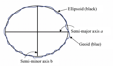
Figure 1 – Ellipsoid parameters and the geoid

The difference between the geoid and the reference ellipsoid is called the
geoidal undulation. GRS80 is the ellipsoid that best fits the geoid on a global
basis and the undulations between the two surfaces range by ±110m.
2.2 What is a Global Reference Frame?
Prior to the advent of space based measurements, geodetic datums were locally
defined and were sufficient for surveyors working in that local area. Their
origins differed from the geo-centre by hundreds of metres due to regional
deviations in the direction of the plumb line (vertical). These regional datums,
such as ED50 (European Datum 1950) or SAD69 (South American Datum 1969), are
regional ‘best fits’ to the geoids within their areas of validity. However, with
the advent of satellite positioning systems a single, global geodetic datum was
required.
A global datum is based on the Conventional Terrestrial Reference System
(CTRS). An important underlying concept is that reference systems are purely
definitions and must be realised through some defined process. Three
particularly relevant realisations of the CTRS are WGS84 as used for GPS, PZ90
for GLONASS and the International Terrestrial Reference Frame (ITRF).
The origin and axes of these realisations are measured in metres and defined
using the Cartesian coordinate system. The origin coincides with the earth’s
centre of mass; the z axis is aligned parallel to the direction of the
Conventional Terrestrial Pole (CTP); the x and y axes are in the plane of the
equator; the x axis passes through the Greenwich meridian and the y axis
completes the right handed orthogonal coordinate system (see Figure 2).
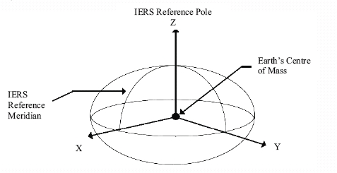
Figure 2 – Right-handed, Earth-centred, Earth-Fixed
orthogonal coordinate system
2.3 Defining the ITRS and Realising the IRTF
The International Terrestrial Reference System (ITRS) is a
conceptual system defined by the International Earth Rotation Service
(IERS). The conceptual ITRS is realised in practice by the coordinates
and velocities of a set of stations on the earth’s surface. The coordinates and
velocity of each station result from various global observation techniques,
including VLBI, SLR, GPS and DORIS. The realisation of the ITRS by the
coordinates and velocities of a particular set of stations, at a particular time
and using a particular set of observations is referred to as the International
Terrestrial Reference Frame (ITRF).
To re-emphasise - concepts and definitions are called ‘reference systems’ and
realisations are called ‘reference frames’.
The IERS, defines ITRF as “the set of points with their 3-dimensional
cartesian coordinates which realize an ideal reference system, the International
Terrestrial Reference System (ITRS) as defined by the IUGG resolution No. 2
adopted in Vienna, 1991.”
Various realisations of the ITRF over time include ITRF89, ITRF90, ITRF91,
ITRF92, ITRF93, ITRF94, ITRF95, ITRF96, ITRF97, ITRF2000, and ITRF2005
1). The successive realisations of ITRF account
for better quantities and qualities of observations, improvements to processing
algorithms and better models of the movements (or velocities) of the tectonic
plates.
There are also many regional densifications of the ITRF such as ETRF89
(European Terrestrial Reference Frame 1989), JGD2000 (Japanese Geodetic Datum
2000), AFREF (African Geodetic Reference Frame), GDA94 (Geodetic Datum of
Australia 1994), etc. GDA94, for example, is based on ITRF92 but realised at an
epoch (in terms of plate tectonics) of 1 January 1994 (an epoch of 1994.0).
1) The number indicates the year of data used in the
realisation.
The World Geodetic System 1984 (WGS84), is the geodetic datum used for the
Global Positioning System (GPS). Given the widespread use of GPS, many users
claim to be working on the WGS84 datum, for example in maritime positioning and
nautical charting.
However, it is important to note that WGS84 is realised and maintained by the
United States Department of Defense. The realisation of WGS84 comes through the
coordinates and velocities used for the US military’s GPS tracking stations but
civilians cannot measure relative to the data from those stations and can
typically only directly access WGS84 via GPS point positions, which may have an
accuracy of several metres.
Fortunately, WGS84 (G11502) ) was
realised to be consistent with ITRF2000 at the few centimetre level and is
maintained consistent with ITRF over time. For civilian users this means that
positions relative to the current ITRF are directly compatible with WGS84.
Similarly, the WGS84 ellipsoid, for all practical purposes, is identical to
the ellipsoid referred to as Geodetic Reference System 1980 (GRS80). GRS80 has a
semi-major axis of 6,378,137 m and a flattening of 1:298.2572221101. This system
was adopted at the XVII General Assembly of the International Union of Geodesy
and Geophysics.
Against this background and considering the context of this guide, a GRS80
ellipsoidal height measured in the current realisation of ITRF can be considered
as equal to a WGS84 ellipsoidal height. Therefore, the ellipsoidal heights used
to realise a vertical reference surface for hydrography should be measured
relative to ITRF and expressed on the GRS80 ellipsoid.
2) The number following the G indicates the GPS week
number of the week during which the coordinates were implemented into the NGA
GPS precise ephemeris estimation process (NGA, 2006).
2.5 Global vertical reference frames
There are approximately one hundred different physical height systems
worldwide all related to different tide gauges. The International Association of
Geodesy (IAG) inter-commission project 1.2, Vertical Reference Frames, is
developing conventions for the unification of regional vertical systems to a
World Height System (WHS). This reference surface is a selected geoid for which
a defined relationship to the sea surface is agreed.
The reference surface for geodetic heights is the ellipsoid. Ellipsoidal
height can only be used as part of a three dimensional ellipsoidal coordinate
system. Simplistically speaking, one can say that global geodetic datums define
a worldwide reference surface for height/depth measurement.
Global vertical reference frames for different applications are being
developed. The idea of a global vertical reference frame is to define W0, the
equipotential reference surface, best fitting the worldwide mean sea surface.
From this, global and regional reference frames are developed such as the Global
Vertical Reference Frame (GVRF) and the European Vertical Reference Frame
(EVRF). The purpose is to connect national height datums to ensure a single
height system across regions.
In the short term, this development does not seem to impinge on hydrographers
who work either with tidal datums or, perhaps more so in the future, with
geodetic datums.
2.6 Tidal Datums – Lowest Astronomical Tide
Technical Resolution A2.5 of the IHO (International Hydrographic
Organisation) resolves that LAT (Lowest Astronomical Tide) shall be adopted as
Chart Datum where tides have an appreciable effect on the water level.
Chart datum is selected as a surface that is so low that the tide will not
frequently fall below it, not so low as to be unrealistic and only gradually
varying between adjacent datums.
Most nations, if not already using approximate LAT, are moving towards its
use. There are some exceptions such as:
- Finland – the tide is practically unobservable
- Greece – minimal tide, Mean Lower Low Water (MLLW) used for Chart Datum
- Japan – use Nearly Lowest Low Water
- USA – use MLLW
Further information can be found in the IHO Manual on Hydrography M13, Ch 5.
3. Definition/creation of a Transformation Model
The creation of a vertical surface separation model (from herein called a
‘separation model’) can range in difficultly from very simple to extremely
complex. A low accuracy, low resolution model can be easily derived using global
tidal and geoid models.
This section will concentrate on the development of a separation model
between Chart Datum and a global geodetic datum (for ease of reference WGS84 is
used but in practice the best available realisation of ITRF should be used).
There are two main steps to the development of a separation model:
- Derivation of the difference between Chart Datum and WGS84 at discrete
points (usually tide stations)
- Interpolation of the difference between those discrete points and
extrapolation of the model for a reasonable distance offshore.
However, these two steps can be fraught with complications.
3.1 Derivation of the Difference between Chart Datum and
WGS84 at Discrete Points
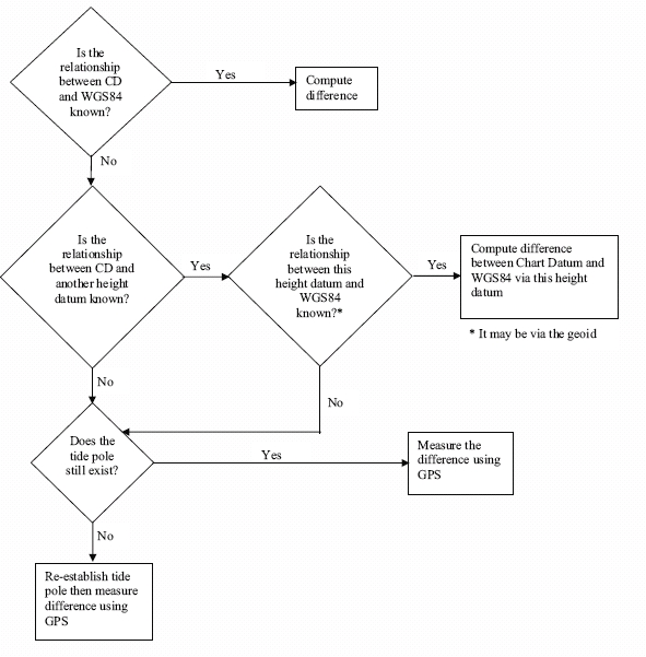
The flowchart at Annex A describes the steps to take but the level of
difficulty will depend on what separation values are already known.
Figure 3 describes the relationship between the vertical surfaces.
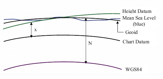
Where
x = height datum/Chart Datum separation
N = geoid/ellipsoid separation
Figure 3 – Relationship between geoid, ellipsoid and
Chart Datum
Other separation values may be known and can be used with the above diagram.
3.2 Extrapolation of the Differences Offshore
Once the differences between Chart Datum and WGS84 have been found this
separation can be extended offshore. It is obvious that the separation will not
be constant and will need modelling. The only exception to this is where the
hydrographic survey is close in-shore and covers only a small area. In this case
the separation throughout the survey area can be considered uniform (e.g. in its
simplest form as an offset).
The variation of tide offshore can be defined using zoning. This will
extrapolate or interpolate the tide or water level variations from the closest
water level station. This may not be necessary depending on the nature of tides
offshore (for example, in the Baltic Sea) but in some regions it is vital. A
study of a hydrodynamic model of the region will give an indication of the
variation of tide/water level offshore.
Co-tidal charts provide an indication of the variation of the time and range
of a tide. They are constructed based on historical data, hydrodynamic models
and other information sources (IHO Manual on Hydrography M13, Chapter 5).
These co-tidal variations can be used in conjunction with the known shore
separation values to model a separation model that extends throughout the area
of interest.
Measuring Tide Offshore
To obtain more accurate separation values offshore tidal datum can be
obtained at discrete points. This approach should be used where the accuracy of
the co-tidal model is not sufficient for the users needs. A common approach for
this is to use GPS and is detailed in IHO Manual on Hydrography M13, Chapter 7.
- “perform wide area GPS static surveys in the selected area;
- “install sufficient tide gauges in the area to obtain details of tidal
datum at these gauge sites computed from long observation periods of data;
- “perform GPS tidal measurements in the survey area at the same time to
obtain a comparable data set of GPS water measurements against conventional
tide gauge measurements;
- “anchor a survey vessel fitted with a RTK Rover Receiver for 25 hour
periods in sufficient locations to generate intermediate datum points within
the area, to allow correlation between the conventional tide gauge methods and
the GPS tidal datum method, and to check any changes in ellipsoid heights
between the RTK stations and the gauge sites over a full tide cycle of 28
days;
- “use a suitable software configuration in the hydrographic survey package
which allows for the ellipsoid separation values to MLLW to be used to compute
tidal height measurements from the waterline of the survey vessel.”
The US Naval Oceanographic Office (NAVOCEANO) use both RTG/RTK GPS equipped
buoys and bottom mounted tide gauges. They recommend 15 days worth of data
(obviously the more the better) that will enable derivation of the four major
tidal constituents.
The GPS equipped buoys have the advantage of being easily deployable and the
data, which is easy to retrieve, is directly related to WGS84 Datum. However,
being small, the buoys are susceptible to severe weather and tampering.
Bottom-mounted tide gauges are difficult to deploy and recover. Data cannot be
retrieved until the gauge is recovered. They do, however, provide very reliable
data.
3.3 Issues with the Development of a Separation Model
The key issue is;
|
PURPOSE - What is the separation model going to be used for?
|
The answer to this question will vary the approach needed and the resources
spent in achieving the aim. There is no point expending time and resources
defining a sub-centimetre separation model when the user only needs decimetre
accuracy.
The development of a separation model needs to consider:
- Achievable accuracy vs. required accuracy
- Resolution of model
- Coverage
- Resource availability
Resource constraints with personnel,
money, equipment and time?
- GNSS network/measurements
How to derive the separation between
Chart Datum and WGS84/ITRF?
- Other extant data sets in the area of interest
Other models,
geoid models, good co-tidal information etc may already exist in the area of
interest. This may affect the approach taken in the development of the
separation model. For example, it may be that a separation model exists for
part of the area of interest: therefore either the model can be developed for
a smaller area or the overlapping model can be used as a quality check on the
model developed for the whole area.
- Storage
It is crucial that the end use of the model is kept in
mind at all times. A separation model is of no use unless the user can use it
in their systems. The model may need to be used in a variety of applications
in which case it should be developed in a generic format.
- Maintenance
The cost of maintaining and updating the model
should be carefully considered. A pragmatic approach should be taken for
updating. The updating regime should reflect the amount of expected change in
the model over time and the accuracy needed by the user. Even annual updates
may be unnecessary and a waste of valued resources.
- Accuracy
The accuracy of the model will depend on many factors
and the total error budget should be kept in mind at all times. All data
contains errors and hence all models have an error associated with them. The
key factor is knowing the errors. The greatest danger is to use data without
knowing how accurate it is. Poor data is not useless data, but it should be
treated according to its accuracy.
For example, the UK co-tidal model has a quoted accuracy of ±0.5m in the
vertical for ranges and therefore any separation model developed using these
can be no more accurate than this.
Tidal models use depth data to develop and refine their models. Charted
depths vary in accuracy and therefore their use should bear in mind their
accuracy.
The GPS measurements relative to a reference station will typically
contribute significantly less error than the errors in the tide modelling.
Even so, care should still be taken with the GPS measurements especially to
avoid systematic errors (multipath, local reference frame issues etc) and
blunders (e.g. antenna height errors).
4. Surveying without Directly Measuring Tides
Hydrographic surveying without directly measuring tides is one of the many
uses a separation model can be used for.
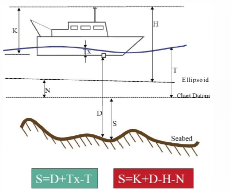
Figure 4 – Surveying formulae for traditional and
non-tide measurement surveying
4.1 Traditional Hydrographic Surveying vs RTK Surveying
In traditional hydrographic surveying sounding depth is measured depth from
the vessel plus heave minus the tide (left hand equation in figure 4)
Using GNSS, such as the real time kinematic technique (RTK), sounding depth
can be obtained by subtracting the height of the vessel’s antenna above the
WGS84 ellipsoid and the ellipsoid/chart datum separation value, N, from the
height of the antenna above the seabed (right hand equation in figure 4). Tide
and, theoretically, heave/squat do not need to be measured
3). Charted depth becomes a derived product.
Therefore, assuming that the surveyor can obtain their depth with respect to
WGS84 accurately enough, including squat, use of the separation model negates
the need to measure tides.
This is the surveying goal – its realisation is currently difficult for two
reasons:
- The accuracy to which the hydrographer can obtain their vertical position
and
- The accuracy of the separation model.
It is clear that surveying without measuring tides is impossible without a
separation model.
Recently NAVOCEANO trialled the ability to map the seabed on a seamless
geocentric reference frame anywhere in the world to IHO Order 1 standards.
Higher accuracies can be obtained using RTK.
There is much research and development in this area and readers are
encouraged to seek relevant conference proceedings to keep abreast with this
novel application. As the ability of the hydrographic surveyor to measure their
vessel with respect to WGS84 increases, this method of surveying without tides
will become more widespread.
3) Note that the height of the antenna above the
transducer, K, and the depth of water below the transducer, D, must both be
corrected to vertical distances on the boat common reference system,
installation offsets and lever arm corrections.
Various nations have developed or are in the process of developing separation
models. Four examples are provided below.
Australia
In Australia, the AUSHYDROID has been developed for Queensland waters (Martin
and Broadbent, 2004). AUSHYDROID is a model of the height of chart datum
relative to the WGS84 ellipsoid (via GPS measurements relative to ITRF). The
separation model has been developed using the known height of the AUSHYDROID at
tidal stations and the interpolation of tide offshore has been done using the
zoning process.
Canada
Canada has been a lead nation in the development of separation models. In the
absence of a geoid that could be used to define the separation model at the
shore tide stations, Canada revisited many tide stations with GPS to calculate
the separation value. Then, using hydrodynamic modelling and satellite altimetry
data, the tide/water level variation off shore was developed (O’Reilly et al,
1996).
United Kingdom
The UK is developing a separation model for UK Waters called VORF, Vertical
Offshore Reference Frame. Its development is nearing completion and further
information will be available in due course from the United Kingdom Hydrographic
Office www.ukho.gov.uk.
VORF has been developed using known shore station separation values
(determined via the UK geoid model) and then realising the separation offshore
using a combination of hydrodynamic models and satellite altimetry data (Adams,
2003). All surfaces are modelled with respect to the GRS80 ellipsoid in order to
enhance the use of VORF in conjunction with precision GNSS heighting.
The following figure shows the provisional results of the difference between
Mean Sea Level and ETRS89.
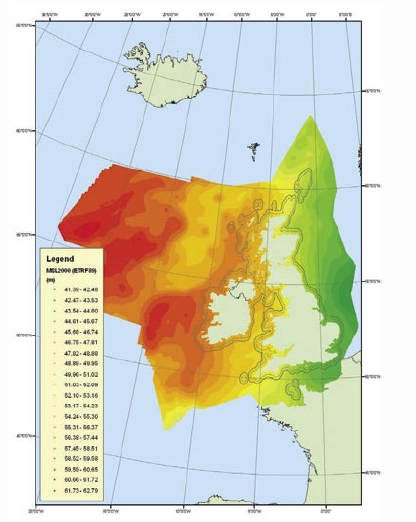
Provisional differences between MSL and ETRS89 in UK waters
(M Ziebart, personal correspondence, 2006).
United States of America
For many years the United States has been developing its VDatum capability.
VDatum is the tool by which users can transform between 28 tidal, orthometric
and ellipsoidal vertical datums (Myers et al, 2005) see figure below. It is
obvious that the main effort is concentrated on the development of tidal datums
and their relationship to a stable reference frame.
To support this the United States’ National Oceanic and Atmospheric
Administration (NOAA) developed a Chart Datum model in Tampa Bay and Delaware
Bays using a hydrodynamic tidal model and a known relationship to NAD83 (Parker,
2002, Hess et al, 2003, Gesch, 2002). NOAA is now using this methodology to
extend it further round the coast of Continental US (Parker et al, 2003). VDatum
applications currently exist in Tampa Bay, Los Angeles, New York Bight, Delaware
Bay, Puget Sound and California (Myers et al, 2005).
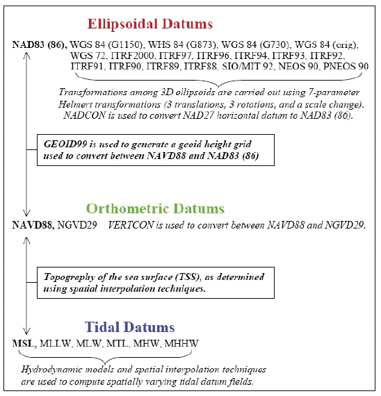
VDatum transformation (Myers et al, 2005)
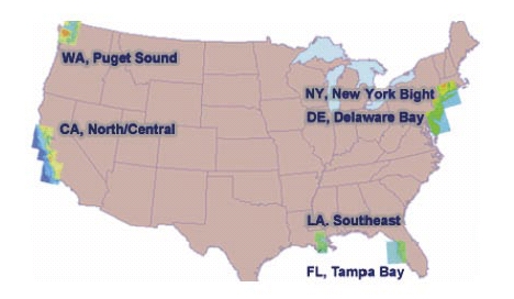
Coverage of VDatum (Myers et al, 2005)
It is well known that other nations have developed or are developing
separation models for their area of interest. This is a key research and
developmental area.
Glossary
CTRS – Conventional Terrestrial Reference System
DORIS – Doppler Orbitography and Radiopositioning Integrated by Satellite
GNSS – Global Navigation Satellite Systems
GPS – Global Positioning System
IERS – International Earth Rotation Reference Systems Service
IHO – International Hydrographic Organization
ITRF – International Terrestrial Reference Frame
ITRS – International Terrestrial Reference Surface
LLR – Lunar Laser Ranging
MLLW – Mean Lower Low Water
MLW – Mean Low Water
RTG – Real Time Gipsy
RTK – Real Time Kinematic
SLR – Satellite Laser Ranging
VLBI – Very Long Baseline Interferometery
WGS84 – World Geodetic System 1984
Useful links
- “Mapping the Seabed on an Absolute Reference Frame System Using the
Real-Time Gipsy (RTG) Global Differential GPS and RTK Positioning.” NAVO
Navigator, Spring 2006.
http://www.navo.hpc.mil/Navigator/sp06_Feature4.html
- International Hydrographic Organisation (1998). “IHO Standards for
Hydrographic Surveys” S44, 4th edition
http://www.iho.shom.fr/
- McCarthy, D. D. and Petit, G. (eds.): IERS Conventions (2003), IERS
Technical Note 32. 2004
http://www.iers.org/MainDisp.csl?pid=46-25776
- “Geodesy for the Layman”, published by NGA, National
Geospatial-Intelligence Agency
http://earth-info.nga.mil/GandG/publications/geolay/toc.html.
- The International Hydrographic Organisation (IHO), Manual of Hydrography
(M13) chapter 2.
http://www.iho.shom.fr/PUBLICATIONS/download_M13.htm
- Further information on WGS84 can be found at the National
Geospatial-Intelligence website
http://earth-info.nga.mil/GandG/publications/puborder.html in particular
TR8350.2
http://earth-info.nga.mil/GandG/publications/tr8350.2/tr8350_2.html
(NGA, 2006).
- IERS, define ITRF as “the set of points with their 3-dimensional cartesian
coordinates which realize an ideal reference system, the International
Terrestrial Reference System (ITRS) as defined by the IUGG resolution No. 2
adopted in Vienna, 1991.”
http://www.iers.org/MainDisp.csl?pid=42-17
Information on Reference Frames in Practice can be found:
- On the FIG Commission 5 website
http://www.fig.net/commission5/wg52/ (An FIG Commission 5 paper contains
at Appendix 1 FIG Fact Sheet 5.501 “The World Geodetic System of 1984” which
describes how to work with WGS84and,
- On the International Association of Geodesy website (Sub-commission 1.2,
Global Reference Frames) at
http://iag.dgfi.badw.de/index.php?id=36.
- International Association of Geodesy inter-commission project 1.2,
Vertical Reference Frames
http://iag.dgfi.badw.de/index.php?id=60
References
- Adams, R. (2003). “Seamless Digital Data and Vertical Datums.” Proceedings
of the FIG Working Week, Paris, France, 13-17 April 2003.
- Adams, R. El-Rabbany, A (2004). “Development of a Seamless Vertical
Reference Surface – Practicalities and Problems.” Proceedings of the FIG
Working Week, Athens, Greece, 22-27 May 2004.
- Arroyo-Suárez, E.N., M.F. van Norden and C. Saxon (2006). “Mapping the
Seabed on an Absolute Reference Frame System Using the Real-Time Gipsy (RTG)
Global Differential GPS and RTK Positioning.” NAVO Navigator, Spring 2006.
- Cross, P. Higgins, M and Lott, R (2000). “Reference Frames in Practice:
The Role of Professional, Scientific, Standards and Commercial Organisations.”
Proceedings of FIG Working Week 2000, 21-26 May, Prague
- El-Rabbany, A. (2005). “Analysis of Hydrographic Data Uncertainty for
Seamless Reference Surface.” Proceedings of the FIG Working Week, Cairo,
Egypt, April 16-21 2005.
- Gesch, D. and R. Wilson (2002). “Development of a Seamless Multisource
Topographic/Bathymetric Elevation Model of Tampa Bay.” MTS Journal, Vol. 35,
No. 4.
- Hess, K.W., D.G. Milbert, S.K. Gill, and D.R. Roman (2003). “Vertical
Datum Transformations for Kinematic GPS Hydrographic Surveys.” Proceedings of
the U.S. Hydro 2003 Conference, Biloxi, Mississippi, USA, 24-27 March. CD-ROM.
- Mann, D. and Whatrup, C. (2005). “The use of Wide Area DGPS as an aid in
tidal modelling.” Proceedings of Shallow Survey 2005, Plymouth, UK, 12-15 Sept
2005.
- Martin, R.J. and G.J. Broadbent, (2004) “Chart Datum for Hydrography.” The
Hydrographic Journal, No. 112.
- Myers, E., A. Wong, K. Hess, S. White, E. Spargo, J. Feyen, Z. Yang, P.
Richardson, C. Auer, J. Sellars, J. Woolard, D. Roman, S. Gill, C. Zervas and
K Tronvig (2005) “Development of a National Vdatum, and it’s Application to
Sea Level Rise in North Carolina.” Proceedings of the US Hydro2005, March
29-31, 2005, San Diego, US.
- National Geospatial-Intelligence Agency (2000 and 2006) “TR8350.2: DoD
World Geodetic System 1984 - Its Definition and Relationships with Local
Geodetic Systems.” Third Edition, 4 July 1997 (Change pages released 3 Jan
2000) plus addendum
http://earth-info.nga.mil/GandG/publications/tr8350.2/tr8350_2.html
- National Geospatial-Intelligence Agency (2005). “Geodesy for the Layman”
TR80-003.
http://earth-info.nga.mil/GandG/publications/geolay/toc.html
- O’Reilly, C., S. Parsons and D. Langelier (1996). “A Seamless Vertical
Reference Surface for Hydrographic Data Acquisition and Information
Management.” Proceedings of the Canadian Hydrographic Conference ’96, Halifax,
N.S., pp. 26-33.
- Parker, B. (2002). “The Integration of Bathymetry, Topography and
Shoreline and the Vertical Datum Transformations Behind It.” International
Hydrographic Review, Vol 3, No. 3.
- Parker, B., K. Hess, D. Milbert and S, Gill (2003). “A National Vertical
Datum Transformation Tool.” Sea Technology, Vol 44, No 9, pp. 10-15. September
2003.
- Van Norden, M.F., E.N. Arroyo-Suárez, A.S. Najjar, (2005), “Hydrographic
Surveys to IHO Standards without Shore Stations using the Real-time Gipsy
(RTG) Global Positioning System (GPS).” Proceedings of the US Hydro2005, March
29-31, 2005, San Diego, US.
Further reading
- Arroyo-Suarez, E., G. Glang, J. Riley, and D. Mabey (2005). “Evaluating a
Global Differential GPS System for Hydrographic Surveying.” Proceedings of the
Institute of Navigation Global Navigation Satellite System (GNSS) Conference
2005, 21-24 September 2005, Long Beach, California.
- Arroyo-Suarez, E., Mabey, D.L., Hsiao, V., Philip, R. (2005)
“Implementation of a Positioning and Telemetry Buoy to Determine Chart Datum
for Hydrographic Survey Applications.” Proceedings of the Institute of
Navigation Global Navigation Satellite System (GNSS) Conference 2005, 21-24
September 2005, Long Beach, California.
- Barritt, C. (2001). “The State and Coastal Surveying – Surveys for safety
of navigation in coastal waters.” Hydro International, Vol. 5, No. 5.
- Bisnath, S., D. Wells, S. Howden, D. Dodd and D. Wiesenburg, (2004),
“Development of an Operational RTK GPS-Equiped Buoy for Tidal Datum
Determination.” International Hydrographic Review, Vol. 5, No. 1 (New Series),
April 2004.
- Canter, P., L. Lalumiere, (2005), “Hydrographic Surveying on the Ellipsoid
with Intertially-Aided RTK.” Proceedings of the US Hydro2005, March 29-31,
2005, San Diego, US.
- El-Rabbany, A. (2002). Introduction to GPS: The Global Positioning System.
Artech House Publishers, Boston, USA.
- El-Rabbany, A. (2003). “Development of a Seamless Vertical Reference
System: Challenges and Opportunities.” Proceedings of the FIG Working Week,
Paris, France, 13-17 April 2003.
- Hughes Clarke, J.E., P. Dare, J. Beaudoin, J. Barlett, (2005) “A Stable
Vertical Reference for Bathymetric Surveying and Tidal Analysis in the High
Arctic.” Proceedings of the US Hydro2005, March 29-31, 2005, San Diego, US.
- Makinen, J., (2004). “Some Remarks and Proposal on the Re-Definition of
the EVRS and EVRF.” Paper presented to the Technical Working Group of the IAG
Subcommission of the European Reference Frame (EUREF), Bratislava, June 1,
2004.
- McCarthy, D. D. and Petit, G. (eds.): IERS Conventions (2003), IERS
Technical Note 32. 2004
http://www.iers.org/MainDisp.csl?pid=46-25776
- O'Reilly, Charles, Herman Varma and Glen King (2001). "The 3-D Coastline
of the New Millennium: Managing Datums in N-Dimension Space". Vertical
Reference Systems, International Association of Geodesy, IAG Symposia (124),
February 20 - 23, 2001, Cartagena, Colombia, ISBN 3-540-43011-3,
Springer-Verlag Berlin, pp. 276-281.
- Parsons, S. A. and C. T. O'Reilly (1998). "The Application of GPS Derived
Ellipsoidal Heights to Hydrographic Data Acquisition and the Definition of
Tidal Datums". Proceedings of the Canadian Hydrographic Conference '98,
Victoria, British Columbia, March 1998, pp. 256 - 266.
- Sanchez, L., (2005). “Definition and Realisation of the SIRGAS Vertical
Reference System within a Globally Unified Height System.” Proceedings of
Dynamic Planet 2005, Cairns, Australia, August 22-26, 2005.
- Vanicek, P. and E.J. Krakiwsky (1986). Geodesy: The Concepts. 2nd Edition,
North Holland, Amsterdam.
- Wells, D., A. Kleusberg, and P. Vanicek (1996). “A Seamless
Vertical-Reference Surface for Acquisition, Management and Display of ECDIS
Hydrographic Data.” Final contract report for the Canadian Hydrographic
Service, Department of Geodesy and Geomatics Engineering Technical Report No.
179, University of New Brunswick, New Brunswick, Canada, 64 pp.
- Whitfield, M. and J. Pepper (2003). “Integrated Coastal Zone - Data
Research Project.” Proceedings of the U.S. Hydro 2003 Conference, Biloxi,
Mississippi, USA, 24-27 March. CD-ROM.
Steps to Calculating Separation Value between Chart Datum and WGS84 at a
Discrete Point
|