Article of the Month -
December 2012
|
Mobile Laser Scanning on Board Hydrographic Survey Vessels
- Applications and Accuracy Investigations
Volker BÖDER, Thomas P. KERSTEN, Thomas THIES, Arne
SAUER, Germany
1) The first author of the
paper, Volker Böder, died 31 August 2012 in a tragic ship accident on
duty and we would like to remember him on the remarkable research he has
done over the years with the publishing of this article. Volker Boeder
was Vice-Chair of Commission 4, Chair of Working Group 4.3 “Multi-Sensor
Systems for Hydrographic Applications”, and was a very active member of
Commission 4. Among other things he worked on a publication related to
the development of technical guidelines for sensor integration (best
practises). Volker Böder shall be very much missed both as a colleague
and a friend.
Key words: : echo sounder, GNSS, multi beam, sensor
integration, terrestrial laser scanning, vessel
SUMMARY
Due to special conditions and requirements in the Port of Hamburg and
along the river Elbe, which is the most essential entrance for the
economy of Hamburg, the monitoring of erosion and sedimentation in the
Port but also the monitoring and documentation of port facilities are of
major interest.
These tasks require a multi sensor system, which is able to measure
simultaneously above and below water. Below water multi beam echo
sounders in mobile mapping systems are in use to monitor quay walls and
sediments. In general static terrestrial surveying methods or LIDAR
measurements generate the necessary information above the waterline.
Both methods are limited for various reasons.
Experiences of the integration of the terrestrial laser scanner Riegl
VZ-400 into the mobile hydrographical multi sensor system will be
presented in this paper. The pilot study was carried out with the
terrestrial laser scanner Riegl VZ-400 of the HafenCity University
Hamburg (HCU), which has been installed on the survey vessel
“Deepenschriewer III” from the Hamburg Port Authority, and on board the
survey vessel Level-A from the HCU.
For testing the sensor integration selected harbour areas in Hamburg
were scanned to demonstrate the performance of the system. To verify the
accuracy of the kinematic laser scanning system on the ship some
reference data has been additionally scanned with static/terrestrial
laser scanning. The system integration and test procedures including
first results are described in this paper.
1. INTROCUCTION
Three-dimensional geodata are digital information to which a specific
spatial location can be assigned on the earth's surface or in the water.
These geodata provide a substantial part of the knowledge existing in
the modern information and communication society, and which is
increasingly needed on all levels in administration, economy and
science, and by individual citizens. They are the basis of
planning-related actions and their availability is a requirement for
location and investment decisions. This leads to an increasing need for
geodata which meets high requirements such as efficient data collection
(up-to-date and economical data) and extensive availability (fast,
simple, complete, area-covering and large scale).
Therefore, mobile sensor systems (or MMS - Mobile Mapping Systems)
offer an optimal solution for efficient 3D data acquisition in the air
(airplane, helicopter), on the ground (vehicle) and on the water (ship).
In this contribution, a mobile multi sensor system is installed on a
survey vessel with which 3D geodata can be simultaneously acquired above
and below water level. However, this paper focuses on the integration of
a terrestrial laser scanner (TLS) on a ship-based multi sensor system,
which is equipped with navigational and hydrographical sensors. Based on
the new developed survey platform different investigations have been
carried out in a co-operation between the HafenCity University Hamburg
(HCU), the Northern Institute of Advanced Hydrographics (NIAH) GmbH, and
the Hamburg Port Authority (HPA). For this pilot study the terrestrial
laser scanner Riegl VZ-400 was used on the survey vessel
“Deepenschriewer III” of HPA, in order to test the system in typical HPA
applications. Some initial experiences with the integration of a
terrestrial laser scanner into the mobile hydrographic multi sensor
system on a ship have already been described by Boeder et al. (2010).
2. MOBILE MULTI SENSOR SYSTEM ON BOARD THE SURVEY VESSEL
„DEEPENSCHRIEWER III“ (HPA) AND „LEVEL-A“ (HCU)
Modern multi sensor systems on a ship can be equipped as follows:
terrestrial laser scanner for 3D data acquisition above water, multi
beam echo sounder to map seabed structures / topography under water,
GNSS for kinematic positioning of the laser scanner and echo sounder,
and inertial measurement unit (IMU) for determination of the vessels
orientation (roll, pitch, heading) and for supporting and improving the
GNSS accuracy. The spatial vectors between the individual sensor systems
are determined very precisely in a ship coordinate system by geodetic
measuring procedures in order to transform all measurements into a
super-ordinate coordinate system.
The multi sensor system on board the survey vessel “Level-A” (HCU)
and “Deepenschriewer III” (HPA) are similarly designed. The GNSS
correction data for the generation of precise real-time positioning
(networking solution) is provided by an external service (“Level-A”:
SAPOS, “Deepenschriewer III”: Trimble VRS-NOW). Both systems use an IMU
from IXSEA. The HCU uses the IXSEA OCTANS III. The HPA’s system (IXSEA
HYDRINS) generates a more precise course angle and supports a
NMEA-positioning input. The data fusion is accomplished in both systems
using the acquisition and processing software QINSy from the company QPS
(Zeist, the Netherlands). Further information on the hydrographical
multi sensor system of the HCU (HCU HMSS) is summarised in Boeder
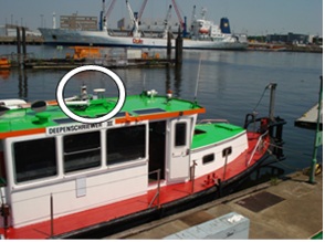
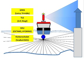
(2010). Fig. 1 shows an overview of the on board sensors and the survey
vessel “Deepenschriewer III”.
|
 |
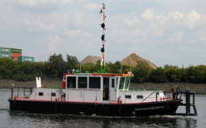 |
Figure 1: Schematical overview of the sensors used on
board “Level-A” and “Deepenschriewer III” (left). Survey vessel
“Deepenschriewer III” (HPA, right)
The “Deepenschriewer III” is a steel ship, which is used by Hamburg
Port Authority (HPA) for hydrographic measurements in the Port of
Hamburg and on the river Elbe. In particular the monitoring of the water
depth as well as the bathymetry of the waters regarding geomorphologic
changes and the detection of obstacles are major tasks for this survey
platform. With a length of 17.2m, a width of 4.9m and a draught of 1.4m
the ship is well suited to almost all surveying applications in the
harbour.
2.1 GNSS-Positioning and IMU-Attitude Determination
The positioning on board is carried out by GNSS systems in real time
using the above mentioned data correction services. In order to achieve
a high availability of precise positioning as many satellites as
possible must be included in the measurements. On board the
“Deepenschriewer III” a Trimble SPS851H GNSS receiver with Zephyr
antenna is operating. The correction data is provided by the service
Trimble VRS-NOW. The measuring rate is up to 20Hz; a PPS output for the
purpose of time synchronisation is available. The accuracies of the
Trimble VRS-NOW correction data service can be estimated to 1-2cm in the
3D point position.
Real time kinematic (RTK) positioning data are integrated into the
IXSEA HYDRINS solution using data from the inertial sensor. The accuracy
of the heading is given with 0.034° in Hamburg (0.02° secant (φ)), roll
and pitch with 0.01°. According to the manufacturer’s specification the
integrated positioning is more precise than the available GNSS solution
by a factor of three. The HYDRINS uses a Kalman filter to combine the
noisy GNSS-data and the long term drifting of the IMU to provide a
smooth and stabile position. However, this statement requires an
independent investigation. The combined solution is then transferred in
real time via RS232 or LAN to the hydrographic processing software QINSy
for the integration of all sensors. On the “Level-A” the determination
of orientation angles can be made additionally with the support of an
array consisting of four GNSS antennas (Boeder 2009).
2.2 Terrestrial Laser Scanner Riegl VZ-400
The terrestrial laser scanner Riegl VZ-400 uses near-infrared light
with a beam divergence of 0.3 mrad (0.017°), which corresponds to one
footprint with a diameter of 30mm at 100m according to the
manufacturer’s specification. The vertical field of view of the VZ-400
ranges from +60° to -40°, which gives a viewing angle of 100° for a 360°
scan. Using these angle values a vertical measuring range of 17.3m over
and 8.4m below the instrument horizon at a distance of 10m can be
determined. However, an additional tilting mount can support other
elevations of the scanning system. The distance between two scan lines
is, at minimum, 4mm in horizontal and vertical directions at a range of
100m.
For the distance measurements a standard deviation of 5mm at 100m
range is specified using Riegl´s test conditions. The resolution of
horizontal and vertical angles is given as 0.0005°, which corresponds to
a lateral deviation of 4mm at a range of 500m. Based on this information
the standard deviation of each coordinate component can be estimated
with a higher precision than 1cm at a range of 100m.
In the Long Range Mode the maximum distance is 500m for good natural
reflectors (reflectivity ρ ≥ 80%) and 160m for reflectors with ρ ≥ 10%.
The effective measurement rate is 42,000 measurements per second with a
pulse repetition rate (PRR) of 100kHz, while this can be speeded up by a
factor of three in the High Speed Mode (125.000 measurements/second, PRR
of 300kHz). Here, the operating range is only 300m, about 60% of the
Long Range Mode using natural reflectors with a reflectivity ρ ≥ 80% and
100m with ρ ≥ 10%.
The scanning speed is indicated as 3 to 120 lines per second in the
vertical. As a consequence an interval of 3cm for vertical lines can be
achieved with a speed of the boat of 3m/s using a scanning speed of 100
lines/s.
The data transfer on board and the time synchronization is solved
similar to the IMAGER 5006i (Boeder 2010). The integration of the Riegl
VZ-400 into the software QINSy had been established without any problems
using the special developed Riegl driver.
2.3 Reson SeaBat 8101
The multi beam echo sounder Reson SeaBat 8101 measures distances in the
water with an acoustic frequency of 240kHz. The beam forming mechanism
generates signals from the received energy with an opening angle of 1.5°
in both the sensor direction and perpendicular to it, corresponding to a
footprint with a diameter of 2.61m at a water depth of 100m. However,
for coastal and riverside applications, which shall be connected to data
from terrestrial laser scanners, depths of approximately 10-20m can be
expected. Therefore, the beam diameter is 26cm at a depth of 10m. Due to
a system expansion the opening angle of the entire multi beam echo
sounder (SeaBat 8101) on the “Level-A” is 210° crosswise and 1.5°
lengthwise to the ship’s longitudinal axis. On board of the
“Deepenschriewer III” the system is equipped with 101 beams as the
standard option using an opening angle of 150°. The maximum range for
measurements is 300m using the available SeaBat 8101.
According to the manufacturer’s specifications the resolution of the
depth measurements is given to 1.25cm. The accuracy of a depth
measurement essentially depends on the accuracy of the determination of
temperature and salinity of the water in the different sediment layers.
In water depths of 10m accuracies of better than 10cm are attainable,
but rarely better than 5cm.
The data can be processed in different post-processing programs,
usually the program QINSy is used on board of the “Level-A” using a LAN
interface for data transfer to the computer.Despite apparently worse
characteristics concerning point measurements in comparison to laser
scanners multi beam echo sounder of good quality are significantly more
expensive than good laser scanners. Here, the less favourable conditions
of the underwater measurements with hydro-acoustic techniques are
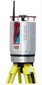
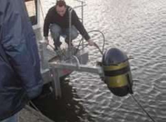
considered. In Fig. 2 the terrestrial laser scanners Riegl VZ-400 and
the multi beam echo sounder Reson SeaBat 8101 are presented, while in
Fig. 3 the system installation on board the ”Deepenschriewer III” are
illustrated.
Figure 2: Riegl VZ-400 (left) and Reson SeaBat 8101
(right)
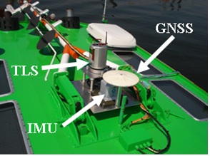
Figure 3: Installation of sensors on board the
“Deepenschriewer III”
Fig. 3 shows the location and the components of the multi sensor
system on the roof of the “Deepenschriewer III”. GNSS antenna, IMU and
TLS were installed on a plate along the ship’s axis with a distance of
30cm between each sensor. The close proximity of each sensor reduces
possible error influences from the geodetic sensor determination and
from the fusion of the measuring data.
The uncertainty computation for the echo sounding part is similar to
the laser scanning part of a hydrographic mobile mapping system. They
differ only in their error sources and error equations and finally in
their magnitudes if both are scaled to 95% confidence level as shown in
Figure 4.
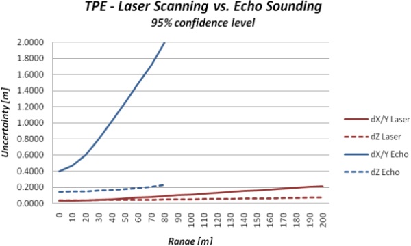
Figure 4: Range depending uncertainty of coordinates
(total propagated error, TPE) of a laser scanning system in comparison
with a multi beam echo sounding system (95% confidence level). (Thies
2011).
To improve the horizontal uncertainty of the echo sounding system
significantly it is necessary to use a high resolution, high frequency
multi beam echo sounder in combination with an IMU. The vertical
uncertainty of such a system is mostly influenced by the accuracy of
sound speed determination which is not only needed for the beam forming
process but also for the ray tracing of the echo beams.
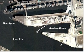
3. SCANNING OF GRASBROOKHAFEN IN THE HAFENCITY OF HAMBURG USING
THE LASER SCANNING SYSTEM RIEGL VZ-400 ON BOARD OF ”DEEPENSCHRIEWER III”
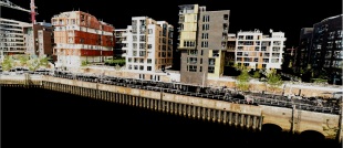
The following presented investigations are based on the first
measurements in the Grasbrookhafen in the HafenCity of Hamburg on July,
16th, 2010. The scanning area is illustrated in Fig. 5 in an outdated
aerial photograph of Google Earth. The harbour basin is about 450m long
in east-west and 60m to 110m broad in north-south direction. With the
exception of the old dock warehouse A of the future Hamburg Philharmonic
Hall no buildings shown on the aerial photograph remained at the time of
survey. However, the northern and the eastern area of the Grasbrookhafen
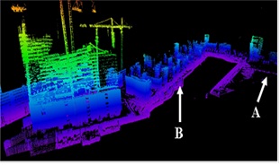
are today already fully developed and in use. The right image in Fig. 5
shows a perspective view of the scanned data in the Grasbrookhafen.
In the first investigations the “Deepenschriewer III” drove at about
20m distance from the quay wall, in order to be able to scan the dock
plants up to the water line. Three profiles were successively scanned
and analysed later in the office. Two profiles 1 and 3 begin on the
northern bank from west to east and conclude with east-west profile on
the southern bank. Profile 2 starts on the northern bank from west to
east and ends on the southern bank with an east west profile.
Figure 5: Outdated aerial photograph of the
Grasbrookhafens (source: Google Earth) in Hamburg HafenCity (left) and
perspective view of the scanned data (right).
4. ACCURACY ANALYSIS
First accuracy analyses could be completed both at the
back-positioned house front and at the quay wall (Fig. 6), which showed
comparable results in each case (7cm in XY, 4cm in Z). The coordinates
of the deviating profile were continuously further distance from the
ship, thus it can be assumed that systematic effects occur in this
profile.
Figure 6: Accuracy analysis at a building and at a quay
wall in the Grasbrookhafen (mark B in Figure 5)
indicating the differences in X, Y and Z.
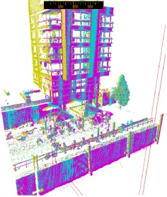
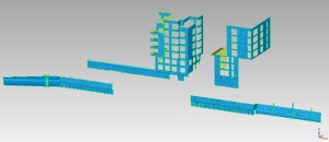
Further precision statements have been accomplished by
analysing surfaces and linear structures in different profiles. The
comparison to reference data which was acquired by static terrestrial
laser scanning with the Riegl VZ-400 on August 13th, 2010 allows more
precise statements about the accuracy of mobile scanning. The aim of the
accuracy analysis is not to determine deviations between discrete points
in mobile and reference data but to give an area based overview of 3D
differences. For this reason four objects were selected out of the whole
dataset which are presented in Figure 7.
Figure 7: Overview of selected objects used for accuracy
analysis: true colour coded reference point cloud (left) and selected
objects, two buildings and two parts of shoreline constructions are
shown as 3D polygon models (right) created with Geomagic (Thies 2011)
The data set has been computed with different processing methods and
their inherent properties, which are summarized below.
- QINSy Online: real-time solution, only online filtered but not
quality assured raw data in IMU position, motion and scan data,
potential latencies in raw data
- QINSy Postprocessing GNSS: online filtered data from replay
functionality, additional quality assured data in GNSS position,
motion, heading tide whereas all detected latencies are compensated
- QINSy Postprocessing IMU: online filtered data from replay
functionality, post processed and quality assured INS trajectory
- RiPROCESS Postprocessing: similar to QINSy Postprocessing IMU,
processed with Riegl software RiProcess
- RiPROCESS Recalibration (Riegl software): contains the results
of the RIEGL scan data adjustment respectively the recalibrated
angular laser misalignments
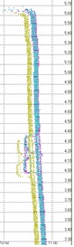
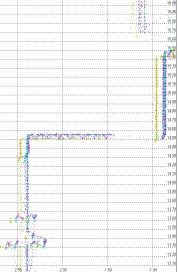
The results between two profiles are analysed in details in Thies
(2011). The best fitting solution of reference and mobile data was
achieved with the Riegl software RiPROCESS Recalibration. Figure 8 shows
the results of the system when all angular misalignments are determined
precisely. The differences are distributed normally which is indicated
by the histogram on the left hand side of the figure. However, there is
still a bias in Y direction of approx. 1 cm but this is just the
accuracy of the positioning system. The vertical deviations were reduced
to ±2cm at maximum which corresponds to the accuracy of the IMU height.
Nevertheless, the deviations oscillate around zero which still indicates
a slight dynamic effect in the motion data.
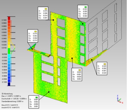
Figure 8: 3D difference
models derived from survey line 1 and 8 datasets processed by RiPROCESS
(Thies 2011)
5. APPLICATIONS FOR MULTI SENSOR SYSTEMS IN THE HARBOUR
Mobile laser scanning on board a hydrographic survey vessel can be
offered for numerous harbour applications, like
- 3D mapping for harbor applications,
- 3D corridor mapping of rivers and its biotopes,
- Topographic survey of coastal shores and river banks,
- Monitoring of dike security and drying-falling tideland areas,
- Determination of the trim behaviour (squat and settlement) of
ship.
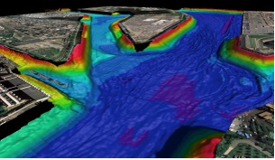
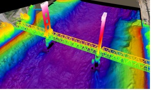
Figure 9 shows the combination of 3D bathymetry combined with
orthophotos and results from a mobile laser scanning of a harbour
bridge. The data can be used in a harbour information system to derive
vertical clearance information under the bridge for ship
manoeuvrability.
Figure 9: 3D bathymetry combined with orthophotos (left)
and vertical clearance information (right) derived from mobile mapping
surveys (Thies 2011)
Figure 10 shows a modelled change analysis of a part of
an old quay wall. Deformations could be monitored by continuous
surveying of endangered objects with mobile laser scanning.
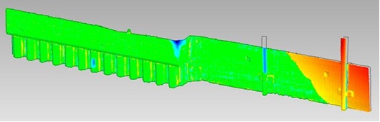
Figure 10: Change analysis of a part of an old quay wall
(Thies 2011)
6. CONCLUSIONS AND OUTLOOK
These investigations into the use of a terrestrial laser scanning
system on board of a surveying vessel in Hamburg show that data
acquisition by such systems can be integrated into the hydrographic
multi sensor systems (HMSS) both in post-processing mode and in
real-time. The high speed of data acquisition, the abundance of
information (3D coordinates, reflecting characteristics) and the
accuracy of the acquired point clouds within the centimetre range offer
good requirements for the use of this new technology for many
applications at and on the water.
For the investigations at HCU and NIAH the software QINSy for data
acquisition plays a crucial key role for the integration of terrestrial
laser scanners in real-time. The integration of the Riegl VZ-400 could
be successfully accomplished. In addition the pilot study showed that
the pure accuracy of the inertial measurement unit significantly affects
the accuracy and quality of the kinematic laser scanning data. Finally,
the laser scanner Riegl VZ-400 used on board the surveying ship has a
clear advantage due to its technical specifications concerning scanning
range, accuracy and resolution, making the use of this laser scanner
very reasonable economically. By system integration and extension of
terrestrial laser scanners on board surveying vessels the range of
applications can be increased.
REFERENCES
Boeder, V., 2009. Untersuchung von Lagewinkelsensoren. Beiträge zum
89. DVW-Seminar Hydrographie – Neue Methoden von der Erfassung zum
Produkt, Hamburg. Schriftenreihe des DVW, Band 58, Wissner-Verlag,
Augsburg, pp. 19-30.
Boeder, V., 2010. HCU-HMSS: A Multi Sensor System in Hydrographic
Applications. 2nd International Conference on Machine Control &
Guidance, Schulze-Lammers, Kuhlmann (Eds.), Bonn, March 9-11, pp. 65-74.
Boeder V., Kersten Th., Hesse C, Thies, Th., Sauer, A., 2010. Initial
Experience with the Integration of a Terrestrial Laser Scanner into the
Mobile Hydrographic Multi Sensor System on a Ship. ISPRS Istanbul
Workshop 2010 on Modeling of optical airborne and spaceborne Sensors, WG
I/4, Oct. 11-13, IAPRS Vol. XXXVIII, part 1/W17.
Thies, T. (2011): A Vessel-Based Mobile Mapping System – From Sensor
Integration to Multipurpose Products. Master Thesis, HafenCity
University Hamburg, 2011 (not published).
BIOGRAPHICAL NOTES
Volker Böder graduated in geodesy from the University Hannover in
1994. His doctoral thesis from 2002 is about precise positioning and
attitude determination in marine applications. He received his Assessor
Degree from the Government of the Federal State of Lower Saxonia in
2005. From 2005 he was professor for practical geodesy and hydrography
at the HafenCity University, Hamburg until his tragic accident.
Thomas P. Kersten graduated in Geodesy from the University of Hanover
in 1988. From 1989 – 1995 he was a research and teaching assistant at
the Swiss Federal Institute of Technology (ETH Zurich), Institute for
Geodesy and Photogrammetry, and from 1995 – 2000 Head of Photogrammetry
Department at Swissphoto Ltd. Since 2001 he is Professor for
Photogrammetry & Laser Scanning at the Hamburg University of Applied
Sciences, and from 2006 he holds the same position at the HafenCity
University Hamburg.
Thomas Thies graduated in Geomatics in 2007 and received his M.Sc.
Hydrography (CAT A) in 2011 from the HafenCity University Hamburg. Since
2007 he is working as a Hydrographic Survey Engineer at the Hydrographic
Survey Department of the Hamburg Port Authority.
Arne Sauer graduated in Geomatics in 2007. Since 2006 he is working
as a Hydrographic Survey Engineer at the Northern Institute of Advanced
Hydrographics at the HafenCity University Hamburg.
CONTACTS
Thomas P. Kersten
HafenCity University Hamburg
Hebebrandstraße 1
22297 Hamburg
GERMANY
Email:
thomas.kersten@hcu-hamburg.de
Thomas Thies
Hamburg Port Authority
Neuer Wandrahm 4
20457 Hamburg
GERMANY
Email:
thomas.thies@hpa.hamburg.de
Arne Sauer
HCU NIAH - Northern Institute of Advanced Hydrographics
Hebebrandstraße 1
22297 Hamburg
GERMANY
Email: arne.sauer@web.de
 |