Article of the Month -
November 2014
|
A Prototype of RFID-Based Cadastral Boundary Mark System (RCBMS) in
Malaysia
Tajul Ariffin MUSA, Abdullah Hisam OMAR, Ivin Amri
MUSLIMAN, Siti Syukriah KHAMDAN, Yip Kit MENG and Kamaludin OMAR,
Malaysia
1) This paper is peer
reviewed and presented at the 2014 FIG Congress in Kuala Lumpur,
Malaysia. The paper discuss an RFID-based cadastral boundary mark system
(RCMBS). The aim of the RCBMS is to modernize the conventional cadastral
boundary marks with marks that are lighter, robust, and easy to locate,
and which offer the capability to perform spatial/non-spatial cadastral
information on site.
SUMMARY
The cadastral system in Malaysia needs to utilize
appropriate technology such as innovation in Information & Communication
Technology (ICT) to efficiently support a modern cadastral system and
infrastructure. Ubiquitous positioning by integrating a multi-sensor and
mobile database management system is an ICT innovation, which can
provide benefits to the cadastral surveying community, such as aiding
users in finding and/or updating information on the cadastral boundary
mark on site. In this paper, an RFID-based cadastral boundary mark
system (RCMBS) is discussed. The main aim of the RCBMS is to modernize
the conventional cadastral boundary marks with marks that are lighter,
robust, and easy to locate, and which offer the capability to perform
spatial/non-spatial cadastral information on site. The RCMBS contains
few subsystems and each component of the subsystem needs to be developed
in order to execute the system. A prototype platform of the RCBMS has
been produced to gather more information, demonstrate the functionality
to help solidify requirements, and technically understand the problems
of the system. It is expected that the RCBMS will provide a valuable
support for cadastral practice in the country.
1. INTRODUCTION
The technical future of cadastre was explored in the
1990s and resulted in ‘Cadastre 2014’ – a blueprint of technical
advancement which is a very useful guide to plan for future development
of the land administration system. The vision of Cadastre 2014 is to
present a comprehensive land recording system in order to replace the
traditional institution of ‘Cadastre’ and ‘Land Registration’ (Kaufman &
Steudler, 1998). The Malaysian government intends to implement Cadastre
2014 in its land registration system and cadastral data management. In
Malaysia, there are two organizations that are responsible for managing
and maintaining the cadastre system: (1) The Department of Survey and
Mapping Malaysia (DSMM) – responsible for preparing, producing and
managing the cadastral spatial information including the surveying and
mapping of the cadastre parcels; and (2) The Land Office (LO) –
responsible for managing cadastral attribute information. To move toward
Cadastre 2014, the Malaysian government has introduced and implemented
two systems; the land registration system called e-Tanah by the LO and
e-Kadaster by the DSMM. These two systems are considered as
stepping-stones toward the modernization of the cadastre system in
Malaysia. In the case of e-Kadaster, all the six (6) statements of
Cadastre 2014 have been explicitly executed (Hua, et al., 2012).
The cadastral system in Malaysia needs to make use of
appropriate technology such as innovation in ICT to efficiently support
the modern cadastral system and infrastructure. Ubiquitous positioning
by integrating a multi-sensor and mobile database management system is
an ICT innovation, which can provide benefits to the cadastral surveying
community, such as aiding users in finding and/or updating information
on cadastral boundary marks on site. Tcha (2006) proposed the
possibility to acquire cadastral information by wireless network
utilizing Radio Frequency Identification (RFID), which can be installed
in the boundary mark. However, superior Internet service and coverage
must be ensured to capture the information for the application of this
proposed approach. Musliman et al. (2012) use an approach of a low-cost
ubiquitous positioning by integrating a multi-sensor and online database
in a single system in order to locate and retrieve information of
cadastral boundary marks on site, in real-time. Their research focuses
on the Malaysia cadastral system with the possibility to apply a
cadastral cell-based concept for the proposed system. In this paper, we
extend the above work on the prototype of RFID-based cadastral boundary
mark system, or simply RCMBS.
This paper is organized into five sections. In
Section 2, the concept of the RCBMS is highlighted. In Section 3,
prototypes of the RFID-based boundary mark and the system applications
are emphasized. Discussion on the needs for a pilot study and the
possibility to test the RCBMS is provided in Section 4. Finally, Section
5 highlights the overall idea and concluding remarks.
2. RCBMS: THE CONCEPT
The main aim of the RCBMS is to modernize the
conventional cadastral boundary mark with marks that are lighter,
robust, and easy to locate, and which offer the capability to perform
spatial/ non-spatial cadastral information on site.
2.1 The Approach
The RCBMS design matters for this study were
conducted in order to achieve the following criteria: (a) ability to
acquire spatial and attributes information of a cadastral boundary mark
directly on site; (b) a low-cost system and minimized time to locate the
cadastral boundary mark and retrieval of cadastral information; (c)
ability to utilize the National Digital Cadastral Database (NDCDB), and
(d) a single system to manage cadastral boundary mark information. The
common approach to achieve the above criteria therefore will consist of
technology update, input of cadastral information, effort on system
development and contribution from the potential user (see Figure 1).
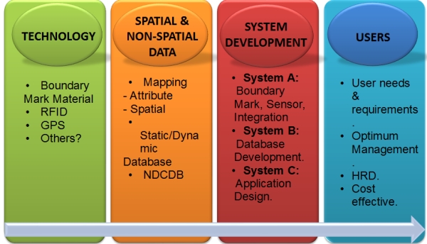
Figure 1: Common approach of the RCBMS.
The RCBMS is adopted as a combination of Global
Positioning System (GPS) and the RFID. Both technologies are
straightforward in terms of application that is to effectively support
the RCBMS user to navigate to the location of the boundary mark and to
retrieve its cadastral information, respectively. The focus is also
given on the materials used in making of the boundary marks where
recyclable materials are preferred, and a technology in material
engineering is applied to produce strong and durable boundary marks at
low-cost.
The DSMM has successfully developed the NDCDB for
Peninsular Malaysia. This national database contains the digital
cadastral information as the backbone for the e-Kadaster by DSMM which
serves cadastral activities in the country. The NDCDB is to be utilized
as the primary data source to facilitate the RCBMS. The challenge is
therefore to synchronize this large database of NDCDB with the mobile
database within the RCBMS.
The development of RCBMS consists of Subsystem A –
multi-sensors integration and design of the RFID-based boundary mark;
Subsystem B – the key to success in the RCBMS is the cadastral boundary
mark management system that deals with cell-based structure to optimize
data query and retrieval from the mobile database; and Subsystem C – to
design mobile applications of RCBMS within the RFID reader processing
unit. Figure 2 illustrates these three subsystems within the RCBMS.
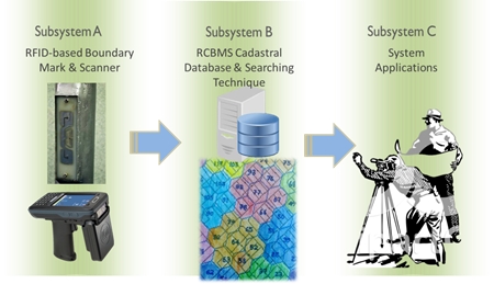
Figure 2: Subsystem of the RCBMS.
The final approach in the RCBMS is to attain the
cooperation amongst the government agency, university and private
sector. The government agencies, specifically the DSMM, work on the
policies, requirements and guidelines to ensure best practice of the
RCBMS amongst the private sector. The university is responsible for
conducting research and providing training for the RCBMS, both for the
government agencies and private sector. The private sector will benefit
from the RCBMS in its cadastral activities, and will also provide
valuable inputs to improve the system. This approach of combining the
interests of the above three parties will ensure best practice and
flexibility of the RCBMS.
2.2 Cadastral Cell-based Concept
Musliman et al. (2012) have proposed a cell-based
concept in order to manage the cadastral data for the RCBMS. The
cell-based concept has been used in the telecommunication industry which
is also referred to as the Global System for Mobile Communication (GSM).
The GSM network is made up of geographic areas. As shown in Figure 3,
these areas include cells, location areas (LAs), mobile services
switching center (MSC) or visitor location register (VLR) service areas
and public land mobile network (PLMN) areas.
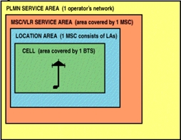
Figure 3: Network Areas.
The cell is the area giving radio coverage by one
base transceiver station. The GSM network identifies each cell via the
cell global identity (CGI) number assigned to each cell. The location
area is a group of cells which is the area in which the subscriber is
paged. Each LA is served by one or more base station controllers, yet
only a single MSC/VLR (refer Figure 4). Each LA is assigned with a
location area identity (LAI) number.
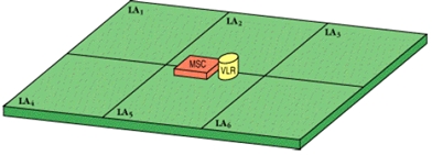
Figure 4: Location Areas.
An MSC/VLR service area represents the part of the
GSM network that is covered by one MSC and which is reachable, as it is
registered in the VLR of the MSC (refer Figure 5).
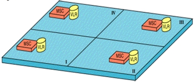
Figure 5: MSC/VLR Service Areas.
Similarly, the spatial cell-based concept can be
applied for the RCBMS with the RFID tagged marker being placed at spots
acting as the MSC/VLR. It is determined that the shape of the cell is
square, grid or hexagon (refer Figure 6). Jeong et al. (2011) have also
utilized the same concept of applying the RFID technology in their
prototype system of a 3D cadastre in Seoul, Republic of Korea.
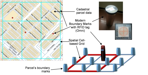
Figure 6: Grid type of spatial cell-based concept.
2.3 Mobile Database for RCBMS
As aforementioned, the Subsystem B of the RCBMS deals
with the cadastral boundary mark management system. In this subsystem
lies the conceptual and physical development of the database in standard
structured query language (SQL) format for mobile database support.
Since a mobile device has storage and processing power limitation, the
use of a mobile database is proposed for committing data changes or
updates as seen in the field. The application also will send RFID tag
information at the current location to retrieve existing NDCDB
information at the server farm in real-time. It is not applicable to
store the whole NDCDB in a mobile device such as in the RFID reader.
Therefore the use of server side scripting is proposed and will be
embedded within the application system architecture. The data format
returned from this server side scripting for NDCDB information is in the
form of JavaScript Object Notation (JSON), i.e. a text-based open
standard design for human-readable data interchange across a
multi-platform. It is derived from the JavaScript scripting language for
representing simple data structures and associative arrays, called
objects.
In the RCBMS, a secondary database engine (MySQL) was
used to support the server side tasks and scripting. The MySQL database
is used to store RFID tag information of boundary marks and its unique
public identifier (UPI) key, which will virtually connect to the
existing NDCDB. The user will send a request to the server via the
application in C# environment. At the server side, each request will be
processed to perform standard structured query language (SQL). The
returned results are the information of an RFID-tagged cadastral lot
with its associated boundary mark and attribute information. The concept
of this application is shown in Figure 7.
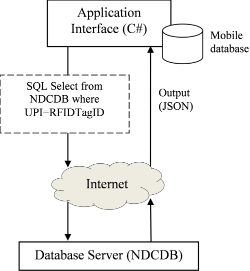
Figure 7: The concept of RCBMS mobile database and query system.
A hypertext preprocessor (PHP) is used to perform the
server side task. Once a user sends a request to the server, the SQL
query will be executed and outputted as JSON data format (as shown in
Figure 8). Figure 9 shows the SQL select function code written in PHP.
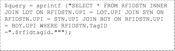
Figure 8: Sample of PHP syntax for data query.
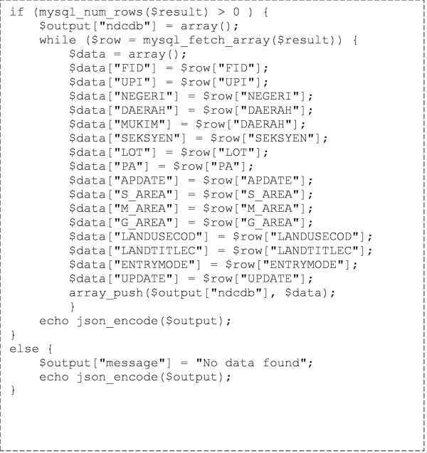
Figure 9: Sample of JSON syntax within PHP for output from database
server.
3. PROTOTYPE COMPONENTS OF RCBMS
As indicated in Section 2, the RCMBS contains several
subsystems and each component needs to be developed in order to execute
the system. The idea is to develop a prototype platform which can gather
more information, demonstrate the functionality to help solidify
requirements and technically understand the problem of the system.
3.1 Prototype 1: RFID-based Boundary Mark
In Prototype 1, the focus is in producing the
cadastral boundary mark itself. For many years, the conventional
cadastral boundary mark has been used in Malaysia. It is made from
concrete in the form of a cylindrical shape with a dimension of 70 mm in
diameter and 600 mm, with a weight of approximately 7 kg. This type of
boundary mark to a certain extent is heavy to transport, brittle and
does not carry any information on site. The main ingredients in
Prototype 1 are chosen from recyclable materials to ensure low-cost
production compared to the conventional concrete type boundary mark.
These recyclable materials consist of palm oil ash (POFA) and pulverized
fuel ash (PFA) (see Figure 10; left).
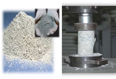
Figure 10: POFA and PFA (left) and compression test (right).
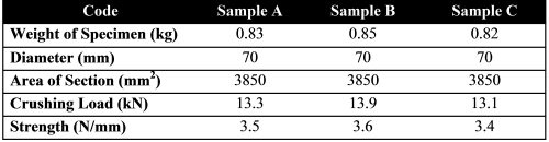
Table 1: Compression test results on three samples of Prototype 1.
Code Sample A Sample B Sample C
Weight of Specimen (kg) 0.83 0.85 0.82
Diameter (mm) 70 70 70
Area of Section (mm2) 3850 3850 3850
Crushing Load (kN) 13.3 13.9 13.1
Strength (N/mm) 3.5 3.6 3.4
The compression test was performed on the three
samples of Prototype 1 (Figure 10; right) by the Civil Engineering
Testing Unit (CETU), Universiti Teknologi Malaysia. The compression test
indicates that all samples have almost similar results (see Table 1),
although Sample B has shown better impact on crushing load and strength.
This could be the reason of the weight of the specimen in Sample B which
is slightly heavier than the other two samples.
Several steps in producing the model of the
RFID-based cadastral boundary mark are shown in Figure 11. While most
steps can be undertaken in between 1 and 2 days, the curing process
requires a longer period of time. In the case of concrete, the duration
of curing depends on the grade and type of materials, mix proportion,
desired strength, shape and size of the concrete member, and
environmental and exposure conditions. The duration may vary from a few
days to a month (Kulkarni & Pereira, 2011). Experience in Prototype 1
has suggested that the curing process is between 7 and 28 days in order
to develop strength and durability of the boundary mark. The final step
in Prototype 1 is to equip the model with the RFID tag. A hard plastic
cover was used to protect the chipped RFID tag and it allows a signal
from the RFID reader to access the tag. The complete model of the
RFID-based cadastral boundary mark with its standard dimension is also
shown in Figure 11.
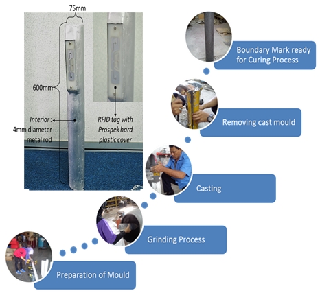
Figure 11: Steps in producing the RFID-based Boundary Mark.
3.2 Prototype 2: The Applications
The RCMBS consists of several applications to
function as a complete system. In Prototype 2, these applications were
developed within the RFID reader by using C# Microsoft Visual Studio
programming language (Figure 12). The source codes of two RCBMS
applications for integration of spatial-attribute cadastral data and
user RFID interface were coded in the RFID reader.
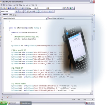
Figure 12: The source code for RCBMS applications.
In the case of the spatial-attribute data
integration, the main task of the source code is to grab the cadastral
attributes once the RFID reader is able to scan the tag ID of the
RFID-based boundary mark (see also Section 2.3). These attributes were
arranged in each individual data table that requires a fast data search
engine through the database. Next, the source code will instruct the
RFID reader to display these attributes and the spatial data
accordingly. Figure 13 demonstrates this application as developed in
Prototype 2 of the RCBMS.
The source code for the user RFID interface is a
command or menu through which a user communicates with the RCBMS via the
RFID reader. The user interface in the RCBMS is a menu-driven interface
in which a user can select command choices from various menus displayed
on the screen of the RFID reader. The user only needs to scan the RFID
tag of the boundary mark in order to activate various menus and to
retrieve the cadastral information provided through the user interface.
Figure 14 shows the user interface of the RCBMS which was developed in
Prototype 2.
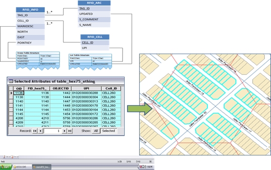
Figure 13: Spatial-attribute data integration and retrieval.
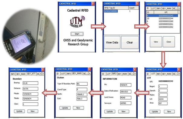
Figure 14: RCBMS user interface.
4. THE NEXT STEPS
There are a few aspects of the RCBMS that require
further investigation. As aforementioned, the main aim of the RCBMS is
to modernize the conventional cadastral boundary mark with marks that
are lighter, robust and easy to locate, and which offer the capability
to perform spatial/non-spatial cadastral information on site. In the
next step of this study, a consideration is given to integrate the GPS
sensor with the RCBMS. The GPS sensor may utilize the coordinates in the
database to navigate the RCBMS user to the location of the boundary
mark. However, the navigation solution as estimated by the GPS sensor
may result in horizontal accuracy up to 17 m at 95% confidence level
(NavCen, 2008). As the location of the current boundary mark is not
necessarily with clear sky viewing conditions, this is a challenging
task for the RCBMS.
Next, it is suggested to improve the crushing load
and strength of the cadastral boundary mark in Prototype 1 (see Table 1)
in order to manage with the condition of the survey work. The
possibility is to mix the recyclable materials with some amount of
composite material such as coarse granular imbedded with cement. It is
predicted that the strength of the materials will be increased but will
be slightly heavier than Prototype 1. Subsequently, the focus must be
given on the dimension of the spatial cell-based grid (see Section 2.2).
The cell dimension is crucial to ensure the effectiveness in data
retrieval from the RCBMS database. A possible solution is to classify
the cadastral lots in that certain area, for example there are different
numbers of cadastral lots in rural and urban areas.
Another important issue in this study is to quantify
the benefits of the RCBMS, and then compare these with the costs
involved, i.e. cost-benefits analysis. In this way, the decision can be
made to proceed or carry out several modifications in each prototype of
the RCBMS. In addition, a small-scale experiment or pilot study could be
highly beneficial during this cost-benefits analysis with a reasonable
sample size of cadastral lots.
5. CONCLUDING REMARKS
This paper briefly summarizes the concept and initial
prototype components of the RFID-based cadastral boundary mark system or
RCMBS. The design approach of the system has taken into account the
technology update, input of cadastral information, and the effort on
system development and contribution from the potential RCBMS users. The
concept of spatial cell-based grid is also explained to manage the
cadastral data in the RCBMS. Moreover, the use of a mobile database is
proposed for committing data changes or updates as seen in the field.
The mobile database is also suitable for the RFID reader device that
usually has storage and processing power limitation. In Prototype 1 of
the RCBMS, the recyclable materials have been used as the main
ingredients in producing the boundary mark. The compression test of
Prototype 1 shows that the sample can deliver up to 13.9 kN and 3.6 N/mm
on crushing load and strength, respectively. In Prototype 2, the source
codes of two RCBMS applications for integration of spatial-attribute
cadastral data and user RFID interface were coded in the RFID reader.
The RCBMS is expected to speed up the time taken that is usually used to
find and/or update the cadastral information on site. Moreover, the
RCBMS can generate revenue from service fees where the user may be able
to retrieve the online cadastral information.
REFERENCES
Hua, T. C., Lim, C. K. and Abdul Halim, N. Z. (2012)
Menanda Aras Kemajuan Sistem Ukur Kadaster Berasaskan Kadaster 2014 -
Persediaan JUPEM ke arah menjayakan Kadaster 2.0. Persidangan
Pengarah-pengarah Ukur 2012, access via http://www.jupem.gov.my/.
Jeong, D.H., Kim, T.J., Nam, D.H., Li, H.S. and Cho,
H.K. (2011) A Review of 3D Cadastre Pilot Project and the Policy of 3D
NSDI in the Republic of Korea. The 2nd International Workshop on 3D
Cadastres, 16th-18th November 2011, Delft, the Netherlands.
Kaufmann, J. and Steudler, D. (1998) Cadastre 2014 –
A Vision for a Future Cadastral System. Working Group 01, Commission 7,
International Federation of Surveyors (FIG).
Kulkarni, S. B. and Pereira, C. (2011) Significance
of Curing of Concrete for Durability of Structures. NBM Construction
Information Portal, access via http://www.nbmcw.com/.
Musliman, I. A., Musa, T. A. and Omar, K. (2012)
Integration of Multi-Sensor for Modern Cadastral Boundary Mark: First
Experience. Buletin Geospatial, MaCGDI, Edisi 2/2012, pp. 6-11.
NavCen, (2008) Global Positioning System Standard
Positioning Service Performance Standard. 4th Ed. US Department of
Defense: Position, Navigation, and Timing Executive Committee.
Washington, DC.
Tcha, D. (2006) A Study on the U-Cadastral Space Data
Modeling in Korea. XXIII International Federation of Surveyors (FIG)
Congress, Munich, Germany, Oct 8-13.
CONTACTS
Dr Tajul Ariffin Musa, Dr Abdullah Hisam Omar
GNSS & Geodynamics Research Group
Faculty of Geoinformation & Real Estate
81310 Universiti Teknologi Malaysia
Johor Bahru, MALAYSIA.
Email: tajul.fksg@gmail.com,
abd_hisham@yahoo.com
Web site:
http://www.geoinfo.utm.my/Research_Group/gng/aboutus.html
 |