Article of the Month -
April 2012
|
Spatial 3D Analysis of Built-up Areas
Oren GAL and Yerach DOYTSHER, Israel
1) This paper is written by Oren
Gal and Yerach Doytsher and has been successfully peer reviewed for the
FIG Working Week May 2012 in Rome, Italy. The paper presents a unique
solution to the 3D visibility problem in built-up areas and will be
presented in the session TS08H - 3D Principles and Technology. Yerach
Doytsher is also chair of FIG Commission 3.
Key words: 3D visibility, spatial analysis, efficient
algorithms, spatial information management
SUMMARY
The paper presents a unique solution to the 3D visibility problem in
built-up areas. A 3D visibility algorithm based on an analytic solution
for basic building structures is introduced. A building structure is
presented as a continuous parameterization approximating of the
building’s corners. The algorithm quickly generates the visible
surfaces' boundary of a single building. Using simple geometric
operations of projections and intersections between visible pyramid
volumes, hidden surfaces between buildings are rapidly computed. The
algorithm, demonstrated with a schematic structure of an urban built-up
environment and compared to the Line of Sight (LOS) method, demonstrates
the computation time efficiency. Whereas the common visibility methods
(LOS approach) require scanning all the object’s points, the presented
solution, by applying the continuous parameterization approximating of
the building’s corners, is successfully avoiding the need to handle each
point separately. As a result, the performance of the presented solution
is much better than the common methods and for the analyzed samples the
improvement time ratio was about 1000 times. The basic building
structure can be modified to complex urban structures by merging
together a number of basic structures.
The main contribution of the presented method in this paper is that
it does not require special hardware, and is suitable for on-line
computations based on the algorithms' performances. The visibility
solution is exact, defining a simple problem that can be a basic form of
other complicated environments.
1. INTRODUCTION
In the last few years, the 3D GIS domain has developed rapidly, and
has become increasingly accessible to different disciplines. 3D Spatial
analysis of Built-up areas seems to be one of the most challenging
topics in the communities currently dealing with spatial data. One of
the most basic problems in spatial analysis is related to visibility
computation in such an environment. Visibility calculation methods aim
to identify the parts visible from a single point, or multiple points,
of objects in the environment.
The visibility problem has been extensively studied over the last
twenty years, due to the importance of visibility in GIS and Geomatics,
computer graphics and computer vision, and robotics. Accurate visibility
computation in 3D environments is a very complicated task demanding a
high computational effort, which can hardly been done in a very short
time using traditional well-known visibility methods (Chrysanthou, 1996;
Plantinga and Dyer, 1990). The exact visibility methods are highly
complex, and cannot be used for fast applications due to the long
computation time. Previous research in visibility computation has been
devoted to open environments using DEM models, representing raster data
in 2.5D (Polyhedral model), and do not challenge or suggest solutions
for dense built-up areas. Most of these works have focused on
approximate visibility computation, enabling fast results using
interpolations of visibility values between points, calculating point
visibility with the LOS method (Doytsher and Shmutter, 1994; Franklin
and Ray, 1994). Other fast algorithms are based on the conservative
Potentially Visible Set (PVS) (Durand, 1999). These methods are not
always completely accurate, as they may include hidden objects' parts as
visible due to various simplifications and heuristics.
A vast number of algorithms have been suggested for speeding up the
process and reducing the computation time (Nagy, 1994). Franklin (2002)
evaluates and approximates visibility for each cell in a DEM model based
on greedy algorithms. An application for siting multiple observers on
terrain for optimal visibility cover was introduced in (Franklin and
Vogt, 2004). Wang et al. (1996) introduced a Grid-based DEM method using
viewshed horizon, saving computation time based on relations between
surfaces and Line Of Sight (LOS), using a similar concept of Dead-Zones
visibility (Cohen-Or and Shaked, 1995). Later on, an extended method for
viewshed computation was presented, using reference planes rather than
sightlines (Wang et al., 2000).
One of the most efficient methods for DEM visibility computation is
based on shadow-casting routine. The routine cast shadowed volumes in
the DEM, like a light bubble (Ratti, 2005). Other methods related to
urban design environment and open space impact treat abstract visibility
analysis in urban environments using DEM, focusing on local areas and
approximate openness (Fisher-Gewirtzman and Wagner, 2003; Yang et al.,
2007). Extensive research treated Digital Terrain Models (DTM) in open
terrains, mainly Triangulated Irregular Network (TIN) and Regular Square
Grid (RSG) structures. Visibility analysis on terrain was classified
into point, line and region visibility, and several algorithms were
introduced based on horizon computation describing visibility boundary
(De Floriani and Magillo, 1994; De Floriani and Magillo, 1999).
Only a few works have treated visibility analysis in urban
environments. A mathematical model of an urban scene, calculating
probabilistic visibility for a given object from a specific viewcell in
the scene, has been presented by (Nadler et al., 1999). This is a very
interesting concept, which extends the traditional deterministic
visibility concept. Nevertheless, the buildings are modeled as circles,
and the main challenges of spatial analysis and building model were not
tackled. Other methods were developed, subject to computer graphics and
vision fields, dealing with exact visibility in 3D scenes, without
considering environmental constraints. Plantinga and Dyer (1990) used
the aspect graph – a graph with all the different views of an
object. Shadow boundaries computation is a very popular method, studied
by (Teller, 1992; Drettakis and Fiume, 1994; Stewart and Ghali, 2000).
All of these works are not applicable to a large scene, due to
computational complexity.
As mentioned, online visibility analysis is a very complicated task.
Recently, off-line visibility analysis, based on preprocessing, was
introduced. Cohen-Or et al. (1998) used a ray-shooting sample to
identify occluded parts. Schaufler et al. (2000) use blocker extensions
to handle occlusion.
In this paper, we introduce a new fast and exact solution to
the 3D visibility problem from a viewpoint in urban environment, which
does not suffer from approximations. We consider a 3D urban environment
building modeled as a cube (3D box) and present analytic solution to the
visibility problem. The algorithm computes the exact visible and hidden
parts from a viewpoint in urban environment, using an analytic solution,
without the expensive computational process of scanning all objects'
points. The algorithm is demonstrated by a schematic structure of an
urban environment, which can also be modified for other complicated
urban environments, with simple topological geometric operators. In such
cases, computation time grows linearly.
Our method uses simple geometric relations between the objects and
the lines connecting the viewpoint and the objects' boundaries by
extending the visibility boundary calculation from 2D to a 3D
environment by using approximated singular points (Elber et al., 2005).
The spatial relationship between the different objects is computed by
using fast visible pyramid volumes from the viewpoint, projected to the
occluded buildings.
The current research tackles the basic case of a single viewpoint in
an urban environment, which consists of buildings that are modeled as
cubes. More complex urban environments can be defined as a union between
the basic structures of several cubes. Further research will focus on
modeling more complex urban environments, and facing multiple viewpoints
for optimal visibility computation in such environments.
2. PROBLEM STATEMENT
We consider the basic visibility problem in a 3D urban environment,
consisting of 3D buildings modeled as 3D cubic parameterization

and viewpoint

Given:
- A viewpoint
in 3D coordinates
- Parameterizations of N objects
describing a 3D urban environment model.
Computes:
- Set of all visible points in
from
This problem seems to be solved by conventional geometric methods,
but as mentioned before, it demands a long computation time. We
introduce a fast and efficient computation solution for a schematic
structure of an urban environment that demonstrates our method.
3. ANALYTIC VISIBILITY COMPUTATION
3.1 Analytic Solution for a Single Object
In this section, we first introduce the visibility solution from a
single point to a single 3D object. This solution is based on an
analytic expression, which significantly improves time computation by
generating the visibility boundary of the object without the need to
scan the entire object’s points.
Our analytic solution for a 3D building model is an extension of the
visibility chart in 2D introduced by Elber et al. (2005) for
continuous curves. For such a curve, the silhouette points, i.e. the
visibility boundary of the object, can be seen in Figure 1:
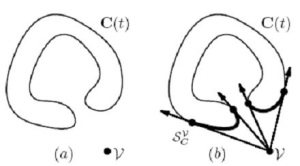
Figure 1: Visible Silhouette Points from viewpoint to curve
(source: Elber et al., 2005)
The visibility chart solution was originally developed for dealing
with the Art Gallery Problem for infinite viewpoint; it is limited to 2D
continuous curves using multivariate solver (Elber et al., 2005), and
cannot be used for on-line application in a 3D environment.
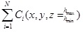
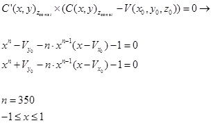
Based on this concept, we define the visibility problem in a 3D
environment for more complex objects as:
 (1) (1)
where 3D model parameterization is
 , and the
viewpoint is given as
. Solutions to
equation (1) generate a visibility boundary from the viewpoint to an
object, based on basic relations between viewing directions from V
to , and the
viewpoint is given as
. Solutions to
equation (1) generate a visibility boundary from the viewpoint to an
object, based on basic relations between viewing directions from V
to  using
cross-product characters. using
cross-product characters.
A three-dimensional urban environment consists mainly of rectangular
buildings, which can hardly be modeled as continuous curves. Moreover,
an analytic solution for a single 3D model becomes more complicated due
to the higher dimension of the problem, and is not always possible.
Object parameterization is therefore a critical issue, allowing us to
find an analytic solution and, using that, to generate the visibility
boundary very fast.
3.1.1 3D Building Model
Most of the common 3D City Models are based on object-oriented
topologies, such as 3D Formal Data Structure (3D FDS), Simplified
Spatial Model (SSS) and Urban Data Model (UDM) (Zlatanova et al., 2002).
These models are very efficient for web-oriented applications. However,
the fact that a building consists of several different basic features
makes it almost impossible to generate analytic representation. Modeling
a 3D urban environment can be done by dividing and simplifying the
environment using a set of grammar rules consisting of basic shape
vocabulary of mass modeling (Stiny, 1982; Wonka et al., 2003; Duarte.,
2002). By that, one can simply create and analyze 3D complex urban
environments by using computerized algorithms.
A three-dimensional building model should be, on the one hand, simple
enabling analytic solution, and on the other hand, as accurate as
possible. We examined several building object parameterizations, and the
preferred candidate was an extended n order sphere coordinates
parameterization, even though such a model is a very complex, and will
necessitate a special analytic solution.
We introduce a model that can be used for analytic solution of the
current problem. The basic building model can be described as:
 (2) (2)
This mathematical model approximates building corners, not as
singular points, but as continuous curves. This building model is
described by equation (2), with the lower order badly approximating the
building corners, as depicted in Figure 2. Corner approximation becomes
more accurate using n = 350 or higher. This approximation enables
us to define an analytic solution to the problem.
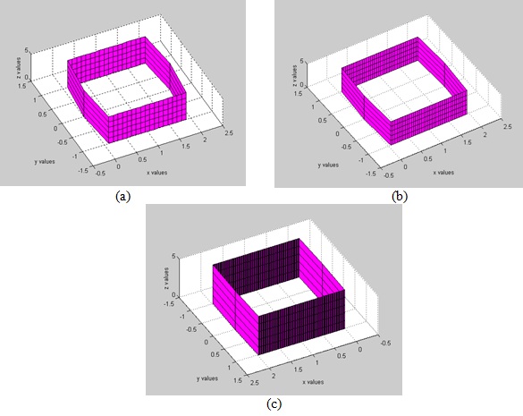
Figure 2: Building model using equation (2) - (a) n = 50;
(b)
n = 200 ; (c) n = 350 .
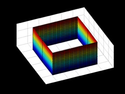
Figure 3: A Three-dimension Analytic Building Model with Equation
(2), where 
We introduce the basic building structure that can be rotated and
extracted using simple matrix operators (Figure 3). Using a rotation
matrix does not affect our visibility algorithm, and for simple
demonstration of our method we present samples of parallel buildings.
3.1.2 Analytic Solution for a Single Building
In this part we demonstrate the analytic solution for a single 3D
building model. As mentioned above, we should integrate building model
parameterization to the visibility statement. After integrating eq. (1)
and(2):
 (3) (3)
where the visibility boundary is the solution for these coupled
equations.
As can be noticed, these equations are not related to Z axis, and the
visibility boundary points are the same ones for each x-y surface due to
the model's characteristics. Later on, we treat the relations between a
building's roof and visibility height in our visibility algorithm, as
part of the visibility computation.
The visibility statement leads to two polynomial order equations,
which appear to be a complex computational task. The real roots of these
polynomial equations are the solution to the visibility boundary. These
equations can be solved efficiently by finding where the polynomial
equation changes its sign and cross zero value; generating the real
roots in a very short time computation (these functions are available in
Matlab, Maple and other mathematical programs languages). Based on the
polynomial cross zero solution, we can compute a fast and exact analytic
solution for the visibility problem from a viewpoint to a 3D building
model. This solution allows us to easily define the Visible Boundary
Points.
Visible Boundary Points (VBP) - we define VBP of the object as
a set of boundary points
 of the visible
surfaces of the object, from viewpoint
. of the visible
surfaces of the object, from viewpoint
.
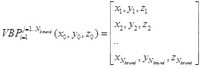 (4) (4)
Roof Visibility – The analytic solution in equation (3) does
not treat the roof visibility of a building. We simply check if
viewpoint height  is
lower or higher than the building height is
lower or higher than the building height
 and use this to
decide if the roof is visible or not: and use this to
decide if the roof is visible or not:
 (5) (5)
If the roof is visible, roof surface boundary points are added to VBP.
Roof visibility is an integral part of VBP computation for each
building.
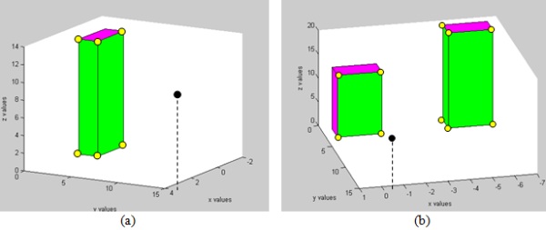
Figure 4: Visibility Volume computed with the Analytic Solution.
Viewpoint is marked in black, visible parts colored in green, and
invisible parts colored in purple. VBP marked with yellow circles - (a)
single building; (b) two non-overlapping buildings.
Two simple cases using the analytic solution from a visibility point
to a building can be seen in Figure 4. The visibility point is marked in
black, the visible parts colored in green, and the invisible parts
colored in purple. The visible volumes are computed immediately with
very low computation effort, without scanning all the model’s points, as
is necessary in LOS-based methods for such a case.
3.2 Visibility Computation in Urban Environments
In the previous sections, we treated a single building case, without
considering hidden surfaces between buildings, i.e. building surface
occluded by other buildings, which directly affect the visibility
volumes solution. In this section, we introduce our concept for dealing
with these spatial relations between buildings, based on our ability to
rapidly compute visibility volume for a single building generating VBP
set.
Hidden surfaces between buildings are simply computed based on
intersections of the visible volumes for each object. The visible
volumes are defined easily using VBP, and are defined, in our case, as
Visible Pyramids. The invisible components of the far building are
computed by intersecting the projection of the closer buildings' VP base
to the far building's VP base as described in 3.2.2.
3.2.1 The Visible Pyramid (VP)
Visible Pyramid (VP) - we define
 of the object
as a 3D pyramid generated by connecting VBP of specific surface j
to a viewpoint . of the object
as a 3D pyramid generated by connecting VBP of specific surface j
to a viewpoint .
Maximum number of  for a single object is three. VP boundary, colored with red arrows, can
be seen in Figure 5.
for a single object is three. VP boundary, colored with red arrows, can
be seen in Figure 5.
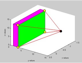
Figure 5: A Visible Pyramid from a viewpoint (marked as a black
point) to VBP of a specific surface
The intersection of VPs allows us to efficiently compute the hidden
surfaces in urban environments, as can be seen in the next sub-section.
3.2.2 Hidden Surfaces between Buildings
As we mentioned earlier, invisible parts of the far buildings are
computed by intersecting the projection of the closer buildings' VP to
the far buildings' VP base. For simplicity, we demonstrate the method
with two buildings from a viewpoint
 one (denoted as
the first one) of which hides, fully or partially, the other (the second
one). one (denoted as
the first one) of which hides, fully or partially, the other (the second
one).
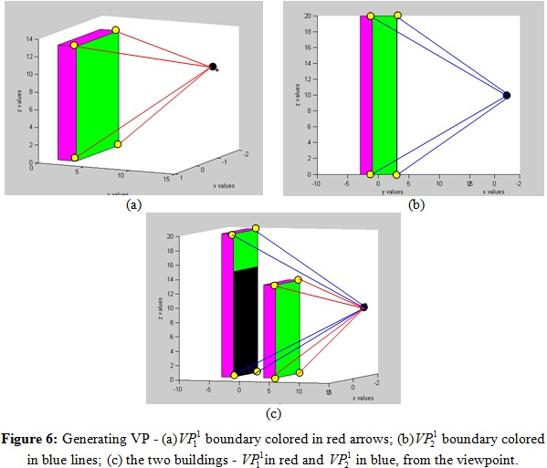
As can be seen in Figure 6, in this case, we first compute VBP for
each building separately,
 ; based on these
VBPs, we generate VPs for each building, ; based on these
VBPs, we generate VPs for each building,
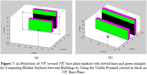
 . After that, we
project . After that, we
project  base to base to
 base plane, as
seen in Figure 7 (a), if existing. At this point, we intersect the
projected surface in
base plane and
update base plane, as
seen in Figure 7 (a), if existing. At this point, we intersect the
projected surface in
base plane and
update  and
(decreasing the
intersected part). The intersected part is the invisible part of the
second building from viewpoint and
(decreasing the
intersected part). The intersected part is the invisible part of the
second building from viewpoint hidden by the first building, which is marked in black in Figure 7 (b).
In the case of a third building, in addition to the buildings
introduced in Figure 7 (b), the projected VP will only be the visible
ones, and the VBP and VP of the second building will be updated
accordingly (as is described in the next sub-section - stage 2.3.4.3) .
We demonstrated a simple case of an occluded building. A general
algorithm for more a complex scenario, which contains the same actions
between all the combinations of VP between the objects, is detailed in
section 3.3. Projection and intersection of 3D pyramids can be done with
simple computational geometry elements, which demand a very low
computation effort.
3.3 Visibility Algorithm Pseudo - Code
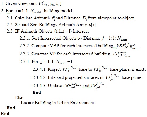
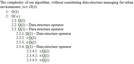
3.4 Visibility Algorithm – Complexity Analysis
We analyze our algorithm complexity based on the pseudo code
presented in the previous section, where represents the number of
buildings. In the worst case, n buildings hide each other.
Visibility complexity consists of generating VBP and VP for n
buildings,  complexity.
Projection and intersection are also
complexity. complexity.
Projection and intersection are also
complexity.
We analyze the visibility algorithm complexity of the LOS methods,
where n represents the number of buildings and k
represents the resolution of the object. The exact visibility
computation requires scanning each object and each object’s points,
 where usually where usually
 . .
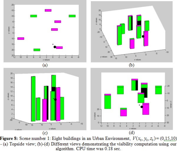
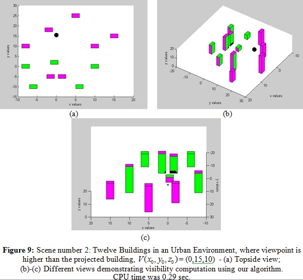
4. RESULTS
We have implemented the presented algorithm and tested some urban
environments on a 1.8GHz Intel Core CPU with Matlab. From the different
tested scenes, only two are shown below. First, we analyzed the
versatility of our algorithm on these scenes with different occluded
elements. After that, we compared our algorithm to the basic LOS
visibility computation, to prove accuracy and computational efficiency.
4.1 Test Scenes
4.2 Computation Time and Comparison to LOS
The main contribution of this research focuses on a fast and accurate
visibility computation in urban environments. We compare our algorithm
time computation with common LOS visibility computation demonstrating
algorithm's computational efficiency.
4.2.1 Visibility Computation Using LOS
The common LOS visibility methods require scanning all objects'
points. For each point, we check if there is a line connecting the
viewpoint to that point which does not cross other objects. We used LOS2
Matlab function, which computes the mutual visibility between two points
on a Digital Elevation Model (DEM). We converted our second test scene
with one to twelve buildings to a DEM, operated LOS2 function, and
measured the CPU time for the visibility computation. Each building
within the DEM was modeled homogenously by 50 points. The visible parts
using the LOS method were the exact parts computed by our algorithm.
Obviously, the total computation time of LOS method was more than 1000
times longer than our analytic solution (3160 seconds vs. 2.9 seconds).
Running times of our analytic solution and the LOS method are depicted
in Figure 10.
Over the last years, efficient LOS-based visibility methods for DEM
models, such as Xdraw, have been introduced in order to generate
approximate solutions (Franklin and Ray, 1994). However, the computation
time of these methods is at least , and, above all, the solution is an approximate one.
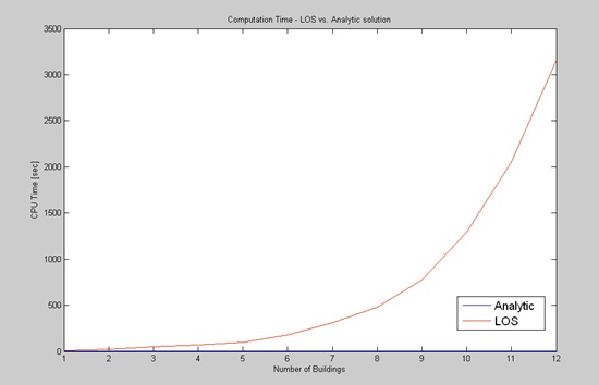
Figure 10: CPU Computation Time of LOS and our algorithm. CPU was
measured in the second scene with an increasing number of buildings from
one to twelve. LOS method was more than 1000 times longer than our
algorithm.
5. CONCLUSIONS AND FUTURE WORK
We have presented an efficient algorithm for visibility computation
in a built-up environment where the built-up environments are
represented by basic structures. The basic structure is modelled with a
mathematical approximating of the buildings’ corners. Our algorithm is
based on a fast visibility boundary computation for a single building,
and on computing the hidden surfaces between buildings by using
projected surfaces and intersections of the visible pyramids. One of the
most important issues of visibility computation relates to the
computational complexity. Complexity analysis of our algorithm has been
presented, as well as a comparison of running times between our
algorithm and the LOS visibility solution, showing a significant
improvement of time performance. The significant improvement in running
time of our algorithm (vs. the LOS method) - shows that its performances
are suitable for on-line and close to real-time applications.
The main contribution of the presented method in the paper is an
exact mathematical solution for the challenging visibility problem
without the need to use any special hardware. The solution which is
based on defining a basic form of urban structures can be applied to
other complicated environments.
Further research will focus on modelling more complex urban
environments and facing multi viewpoints for optimal visibility
computation in such environments, generalizing the presented building
model for more complex ones.
REFERENCES
- Chrysanthou Y., "Shadow Computation for 3D Interactive and
Animation," Ph.D. Dissertation, Department of Computer Science,
College University of London, UK, 1996
- Cohen-Or D., Fibich G., Halperin D., and Zadicario E.,
"Conservative Visibility and Strong Occlusion for Viewspace
Partitioning of Densely Occluded Scenes," In EUROGRAPHICS’98, 1998
- Cohen-Or D. and Shaked A., "Visibility and Dead- Zones in
Digital Terrain Maps," Eurographics, vol. 14(3), pp. 171- 180, 1995
- De Floriani L. and Magillo P., "Visibility Algorithms on
Triangulated Terrain Models," International Journal of Geographic
Information Systems, vol. 8(1), pp. 13-41, 1994
- De Floriani L. and Magillo P., "Intervisibility on Terrains," In
P.A. Longley, M.F. Goodchild, D.J. Maguire & D.W. Rhind (Eds.),
Geographic Information Systems: Principles, Techniques, Management
and Applications,1999, pp. 543-556. John Wiley & Sons
- Doytsher Y. and Shmutter B., "Digital Elevation Model of Dead
Ground," Symposium on Mapping and Geographic Information Systems
(Commission IV of the International Society for Photogrammetry and
Remote Sensing), Athens, Georgia, USA, 1994
- Duarte, J. "Malagueira Grammar – towards a tool for customizing
Alvaro Siza’s mass houses at Malagueira" PhD thesis, MIT School of
Architecture and Planning, 2002
- Drettakis G. and Fiume E., "A Fast Shadow Algorithm for Area
Light Sources Using Backprojection," In Computer Graphics
(Proceedings of SIGGRAPH ’94), 1994, pages 223–230
- Durand F., "3D Visibility: Analytical Study and Applications,"
PhD thesis, Universite Joseph Fourier, Grenoble, France, 1999
- Elber G., Sayegh R., Barequet G. and Martin R., "Two-Dimensional
Visibility Charts for Continuous Curves," Shape Modeling
International 05, MIT, Boston, USA, 2005, pp. 206-215
Fisher-Gewirtzman D. and Wagner I.A., "Spatial Openness as a
Practical Metric for Evaluating Built-up Environments," Environment
and Planning B: Planning and Design vol. 30(1), pp. 37-49, 2003
- Franklin W.R., "Siting Observers on Terrain," in D. Richardson
and P. van Oosterom, eds, Advances in Spatial Data Handling: 10th
International Symposium on Spatial Data Handling. Springer-Verlag,
2002, pp. 109–120
- Franklin W.R. and Ray C., " Higher isn’t Necessarily Better:
Visibility Algorithms and Experiments," In T. C. Waugh & R. G.
Healey (Eds.), Advances in GIS Research: Sixth International
Symposium on Spatial Data Handling, 1994, pp. 751–770. Taylor &
Francis, Edinburgh
- Franklin W.R. and Vogt C., "Multiple Observer Siting on Terrain
with Intervisibility or Lores Data," in XXth Congress, International
Society for Photogrammetry and Remote Sensing. Istanbul, 2004
Nadler B., Fibich G., Lev-Yehudi S. and Cohen-Or D.,"A Qualitative
and Quantitative Visibility Analysis in Urban Scenes," Computers &
Graphics, 1999, pp. 655-666
- Nagy G., "Terrain Visibility," Technical report, Computational
Geometry Lab, ECSE Dept., Rensselaer Polytechnic Institute, 1994
- Plantinga H. and Dyer R., "Visibility, Occlusion, and Aspect
Graph," The International Journal of Computer Vision, vol. 5(2),
pp.137-160, 1990
- Ratti C, "The Lineage of Line: Space Syntax Parameters from the
Analysis of Urban DEMs'," Environment and Planning B: Planning and
Design, vol. 32, pp. 547-566, 2005
- Schaufler G., Dorsey J., Decoret X. and Sillion F.X.,
"Conservative Volumetric Visibility with Occluder Fusion," In
Computer Graphics, Proceedings of SIGGRAPH 2000, pp. 229-238
- Stewart J. and Ghali S., "Fast Computation of Shadow Boundaries
Using Spatial Coherence and Backprojections," In Computer Graphics,
Proceedings of SIGGRAPH 1994, pp. 231-238
- Stiny, G. "Spatial relations and grammars" Environment and
Planning B, 1982, 9, 313–314
- Teller S. J., "Computing the Antipenumbra of an Area Light
Source," Computer Graphics, vol. 26(2), pp.139-148, 1992
- Wang, J., G.J. Robinson, and K. White, "A Fast Solution to Local
Viewshed Computation Using Grid-based Digital Elevation Models,"
Photogrammetric Engineering & Remote Sensing, vol. 62, pp.1157-1164,
1996
- Wang, J., G.J. Robinson, and White K., "Generating Viewsheds
without Using Sightlines," Photogrammetric Engineering & Remote
Sensing, vol. 66, pp. 87-90, 2000
Wonka, P., Wimmer, M., Sillion, F., and Ribarsky, W. "Instant
architecture". ACM Transactions on Graphics 22, 3, 2003, 669–677
- Yang, P.P.J., Putra, S.Y. and Li, W., "Viewsphere: a GIS-based
3D Visibility Analysis for Urban Design Evaluation," Environment and
Planning B: Planning and Design, vol. 43, pp.971-992, 2007
- Zlatanova S., Rahman A., and Wenzhong S., "Topology for 3D
Spatial Objects," International Symposium and Exhibition on
Geoinformation, 2002, pp. 22-24
BIOGRAPHICAL NOTES
Oren Gal received his B.Sc. in Aerospace Engineering, from the
Technion - Israel Institute of Technology in 2004. At 2009 he received
his M.Sc. in Mechanical Engineering also from the Technion. He is
currently PhD candidate in Mapping and Geo-information Engineering at
the Technion. His research interests include spatial analysis of 3D
environments, motion planning in dynamic environments, and Multi-Agents.
Oren's PhD research is entitled "Visibility Analysis in 3D for
Multi-Agent Trajectory Planning".
Prof. Yerach Doytsher graduated from the Technion – Israel
Institute of Technology in Civil Engineering in 1967. He received a
M.Sc. (1972) and D.Sc. (1979) in Geodetic Engineering also from
Technion. Until 1995 he was involved in geodetic and mapping projects
and consultations within the private and public sectors in Israel and
abroad. Since 1996 he is a faculty staff member in Civil Engineering and
Environmental at the Technion, and heads the Geodesy and Mapping
Research Center at the Technion. He is the Chair of FIG Commission 3 on
Spatial Information Management for the term 2011-2014, and is the
President of the Association of Licensed Surveyors in Israel.
CONTACTS
Oren Gal
Mapping and Geo-Information Engineering
Technion – Israel Institute of Technology
Technion City
Haifa 32000, ISRAEL
Tel: +972 57 8119341
Fax + 972 4 8295708
Email: orengal@technion.ac.il
Prof. Yerach Doytsher
Mapping and Geo-Information Engineering
Technion – Israel Institute of Technology
Technion City
Haifa 32000, ISRAEL
Tel. + 972 4 8293183
Fax + 972 4 8295708
Email: doytsher@technion.ac.il
Web site:
http://cee.technion.ac.il/doytsher
 |